Equipment and method for measuring the offset angle of a resolver in a synchronous electric machine

A technology of resolver and angle measurement, applied in the starter of a single synchronous machine, controlling electromechanical transmission, motor generator/starter, etc., can solve the problems of inaccurate calculation of time, greed, etc.

Inactive Publication Date: 2013-01-30
MICHELIN & CO (CIE GEN DES ESTAB MICHELIN)
View PDF6 Cites 27 Cited by
  • Summary
  • Abstract
  • Description
  • Claims
  • Application Information

AI Technical Summary

Problems solved by technology

So the method is imprecise and it is very greedy in terms of computation time

Method used


Image

  • Equipment and method for measuring the offset angle of a resolver in a synchronous electric machine
  • Equipment and method for measuring the offset angle of a resolver in a synchronous electric machine
  • Equipment and method for measuring the offset angle of a resolver in a synchronous electric machine

Examples


Embodiment Construction

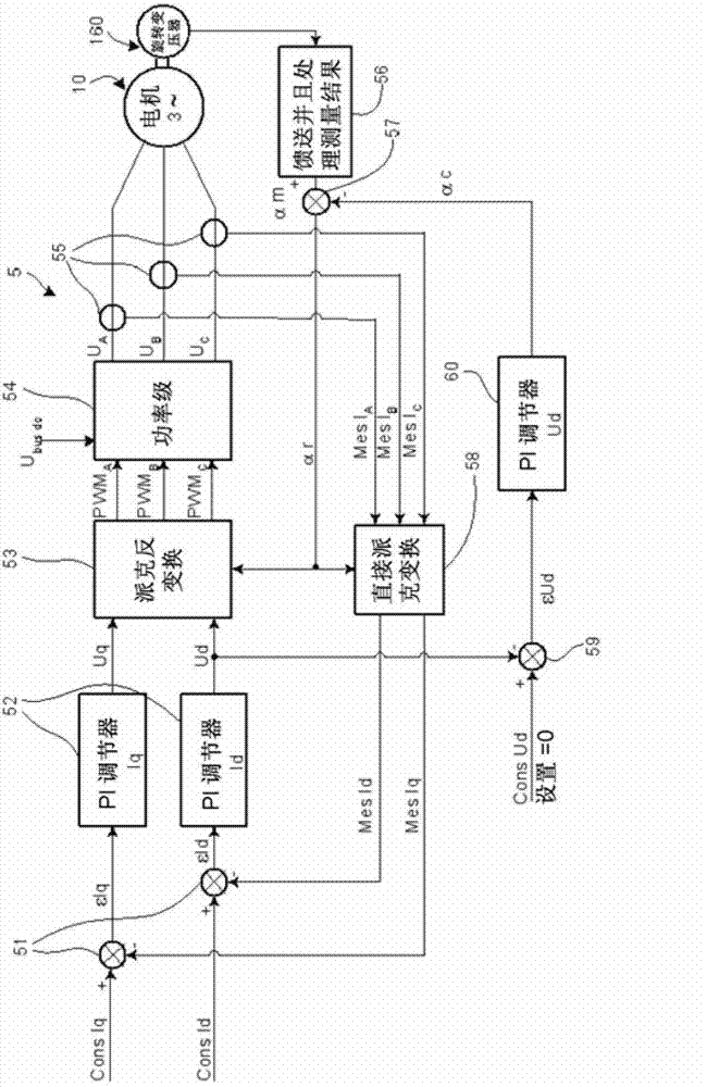
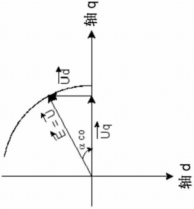
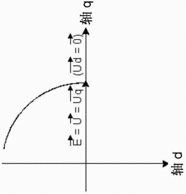
[0027] Let us first show how the measurement of the setting error of the resolver rotor can be made.

[0028] According to conventional means, constant currents are injected into the two phases of, for example, the stator coils. The rotor must be free to rotate, then in a well-defined equilibrium position, the rotor flux is naturally aligned with the generated stator flux. Due to this equilibrium position of the rotor, it is known what the indication value by the position measurement of the resolver should be, and it is therefore possible to deduce from this the error between this imagined measurement and this measurement. This error will have to be eliminated by the resolver setting operation.

[0029] However, this solution exhibits the following drawbacks. Significant current must be injected into the stator to get a practically well-defined rotor position, so there may be significant heating during the set-up procedure. For a multi-pole motor with P pairs of poles, ther...


PUM


Abstract

The invention relates to equipment comprising a first calculation unit (53) for carrying out a inverse Park transform on the basis of the voltages (Uq and Ud) at the output of the PI current controllers (52), outputting electric-voltage set-point signals (PWMA, PWMB et PWMC) into a power stage (54) powered by a line on which a DC voltage (Ubus-dc) is available. The power stage (54) generates a three-phase voltage system (UA, UB and UC) for powering the electric machine (10). The equipment comprises a signal-processing unit (56) that provides an angle measurement (am). A second calculation unit (58) uses the phase currents (Mes IA, Mes IB and Mes lC) and the rotor angle (ar) to output values (MesId and MesIq) used by the first calculation unit (53). A PI voltage controller (60) outputs an angle (ac) for adjusting the setting error by adjusting a set value for the voltage (Ud).

Description

technical field [0001] The present invention relates to rotating electrical machines. The invention is particularly directed to rotating electrical machines with a resolver or with any other sensor capable of measuring absolute angular position, and the invention relates to the initial adjustment of this sensor, such as a resolver. Background technique [0002] When the shaft of the electric machine is equipped with a resolver, which drives the rotor of the resolver, the resolver produces a set of alternating electrical signals at the output of the windings of its stator, the characteristics of the relative amplitudes of these alternating electrical signals are truly and instantaneously Reflects the angular position of the rotor of the motor. In an automatic control motor, this signal is used to control the current in the windings of the stator to maintain the optimal angular difference (typically in quadrature) between the rotating magnetic field in the stator and the magn...

Claims


Application Information

Patent Timeline
Patent Type & Authority Applications(China)
IPC IPC(8): H02P1/46H02P21/00H03M1/10
CPCH02P6/16H02P1/46H02P21/0035H02P21/22
Inventor C·萨维奥J-L·林达B·韦迪
Owner MICHELIN & CO (CIE GEN DES ESTAB MICHELIN)
Why Eureka
Try Eureka