
Magnetic resonance imaging device, magnetic field adjuster for magnetic resonance imaging device, magnetic resonance imaging method, and magnetic field adjustment method for magnetic resonance imaging device

A magnetic resonance imaging and magnetic field adjustment technology, which is applied in the direction of measuring devices, applications, and measuring magnetic variables, can solve problems such as variable length

Active Publication Date: 2013-01-30
TOSHIBA MEDICAL SYST CORP
View PDF9 Cites 2 Cited by
  • Summary
  • Abstract
  • Description
  • Claims
  • Application Information

AI Technical Summary

Problems solved by technology

[0014] On the other hand, in order to ensure the space of the bed, the distance between the static magnetic field magnet and the side wall of the bed in the shielding room must be longer than the distance from the wall on the opposite side of the bed in the shielding room.

Method used


Image

  • Magnetic resonance imaging device, magnetic field adjuster for magnetic resonance imaging device, magnetic resonance imaging method, and magnetic field adjustment method for magnetic resonance imaging device
  • Magnetic resonance imaging device, magnetic field adjuster for magnetic resonance imaging device, magnetic resonance imaging method, and magnetic field adjustment method for magnetic resonance imaging device
  • Magnetic resonance imaging device, magnetic field adjuster for magnetic resonance imaging device, magnetic resonance imaging method, and magnetic field adjustment method for magnetic resonance imaging device

Examples


no. 1 Embodiment approach )

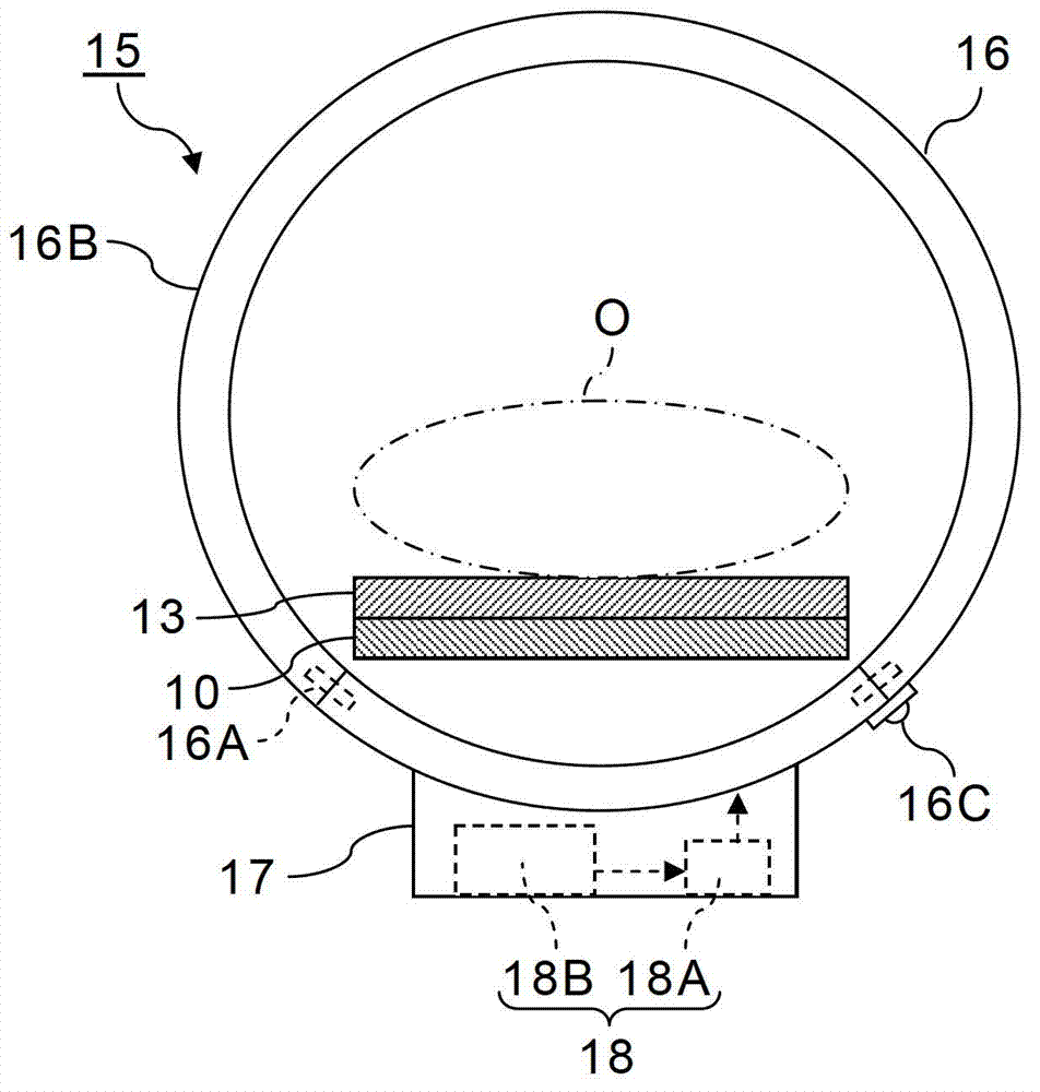
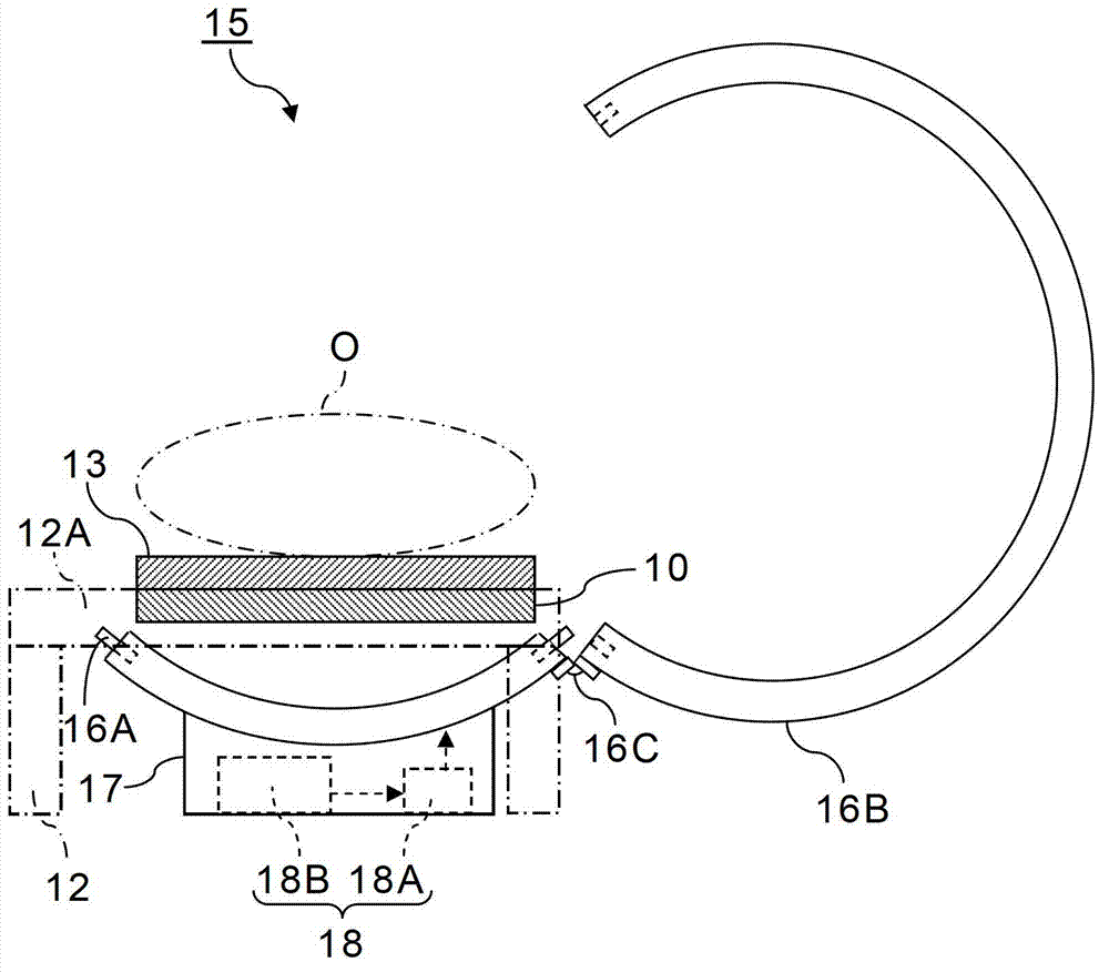
[0034] figure 1 It is a vertical cross-sectional view of the magnetic resonance imaging apparatus and the magnetic field adjuster for the magnetic resonance imaging apparatus according to the first embodiment of the present invention.

[0035] The magnetic resonance imaging apparatus 1 has a data acquisition system 2 and a control system 3 . The data collection system 2 is installed in a shielded room 4 forming a photographic studio. On the other hand, the control system 3 is provided outside the shield room 4 .

[0036] The data collection system 2 has a function of collecting NMR signals from the subject O by applying gradient magnetic field pulses and RF pulses to the subject O placed under a static magnetic field. Therefore, the data collection system 2 has a gantry (stand) 5 and a bed 6 . An imaging area is formed on the gantry 5, and a cylindrical static magnetic field magnet 7, a cylindrical gradient magnetic field coil 8, a cylindrical whole body (WB: whole body) co...

no. 2 Embodiment approach )

[0084] Figure 6 It is a longitudinal sectional view of a magnetic resonance imaging apparatus and a magnetic field adjustment member for a magnetic resonance imaging apparatus according to a second embodiment of the present invention, Figure 7 yes Figure 6 Left side view of field trim shown.

[0085] Figure 6 and Figure 7 The magnetic resonance imaging apparatus 1 and magnetic field adjuster 15A of the second embodiment shown differ from the magnetic resonance imaging apparatus 1 and magnetic field adjuster 15 of the first embodiment only in the configuration of the magnetic field adjuster 15A. Therefore, only the configuration of the magnetic field adjustment member 15A will be described, and the other components will be given the same reference numerals and their descriptions will be omitted.

[0086] The magnetic field adjuster 15A of the second embodiment is configured such that a ferromagnetic body of a desired shape that improves the uniformity of the static mag...

no. 3 Embodiment approach )

[0100] Figure 10 It is a longitudinal sectional view of a magnetic resonance imaging apparatus and a magnetic field adjuster for the magnetic resonance imaging apparatus according to a third embodiment of the present invention.

[0101] exist Figure 10 The magnetic resonance imaging apparatus 1 of the third embodiment shown is different from the magnetic resonance imaging apparatus 1 of the first and second embodiments only in the configuration of the magnetic field adjustment members 15 , 15A. Therefore, only the configuration of the magnetic field adjusters 15 and 15A will be described, and the description of other components will be omitted by denoting the same reference numerals.

[0102] In the magnetic resonance imaging apparatus 1 of the third embodiment, as the first magnetic field adjuster 15, Figure 4 The illustrated cancel coil 16 for improving the uniformity of the static magnetic field is provided on the opposite side of the bed 6 from the NMR signal collecti...


PUM


Abstract

This magnetic field adjuster for a magnetic resonance imaging device set forth in an embodiment is provided with a magnetic field adjustment unit and an installation unit. The magnetic field adjustment unit is disposed outside of the magnets of the magnetic resonance imaging device, and improves the uniformity of a static magnetic field formed by the magnets under the influence of the environment inside a shield room where the magnets are installed. The installation unit installs the magnetic field adjustment unit outside of the magnets. In addition, the magnetic resonance imaging device set forth in the embodiment is provided with an imaging unit and a magnetic field adjustment unit. The imaging unit forms a static field by means of magnets, and performs magnetic resonance imaging by collecting magnetic resonance signals from a subject, said signals having been sent to a collection area for magnetic resonance signals which are to be formed inside the magnets by a table. The magnetic field adjustment unit is disposed on the outside of the magnets, and improves the uniformity of a static magnetic field formed by the magnets under the influence of the environment inside a shield room where the magnets are installed.

Description

technical field [0001] Embodiments of the present invention relate to a magnetic resonance imaging (MRI: Magnetic Resonance Imaging) apparatus, a magnetic field adjuster for the magnetic resonance imaging apparatus, a magnetic resonance imaging method, and a magnetic field adjustment method for the magnetic resonance imaging apparatus. Background technique [0002] MRI is a kind of high-frequency (RF: radio frequency) signal of Larmor frequency to magnetically excite the nuclear spin (Nuclear Spin) of the subject placed in a static magnetic field, and the nuclear magnetic resonance (NMR) accompanying this excitation is produced. NMR (nuclear magnetic resonance) signal reconstructed image imaging method. [0003] The static magnetic field guide magnet included in the MRI apparatus generates a high-intensity static magnetic field for imaging. Therefore, in order to avoid magnetic influences on surrounding electronic equipment, the MRI apparatus is installed in an imaging room...

Claims


Application Information

Patent Timeline
IPC IPC(8): A61B5/055
CPCG01R33/421A61B5/0046A61B5/055G01R33/3873G01R33/387G01R33/3875
Inventor 高见正平坂仓良知野上和人田中秀和
Owner TOSHIBA MEDICAL SYST CORP
Learn More