
Modification of atomic force microscopy tips by deposition of nanoparticles with an aggregate source

A nanoparticle and ion cluster technology, applied in nanotechnology, nanotechnology, nanotechnology and other directions for sensing, can solve problems such as not allowing and modifying probes, and achieve easy implementation, good resolution and functionalization. Effect

Inactive Publication Date: 2013-01-23
CONSEJO SUPERIOR DE INVESTIGACIONES CIENTIFICAS (CSIC)
View PDF3 Cites 0 Cited by
  • Summary
  • Abstract
  • Description
  • Claims
  • Application Information

AI Technical Summary

Problems solved by technology

It must be emphasized that such modifications do not allow an easy way to modify the chemical properties of the probes for specific applications

Method used


Image

  • Modification of atomic force microscopy tips by deposition of nanoparticles with an aggregate source
  • Modification of atomic force microscopy tips by deposition of nanoparticles with an aggregate source
  • Modification of atomic force microscopy tips by deposition of nanoparticles with an aggregate source

Examples


Embodiment Construction

[0023] The invention will be illustrated below by means of a number of tests carried out by the inventors, clearly showing the characteristics and effects of the method of the invention for coating or modifying the surface of an AFM probe.

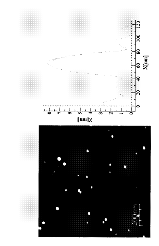
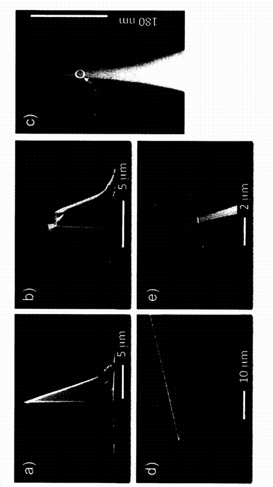
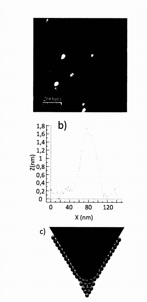
[0024] The tests were conducted to compare AFM images obtained with unmodified commercial AFM probes with AFM images obtained with commercial probes modified by depositing nanoparticles generated by the ion cluster source.

[0025] Under ultra-high vacuum conditions using an ion cluster source produced by Oxford Applied Research and Co 95 Au 5 Alloy blanks are deposited.

[0026] The nanoparticle production process was optimized to produce 2-3 nm spherical nanoparticles by means of ICS. For this, the relevant parameters are as follows: power applied to the magnetron: 20 W; cluster length: 50 mm; argon gas flow: 60 sccm; helium gas flow: 50 sccm; distance between ion cluster source and AFM probe: 190 mm; deposition time :2 minutes. ima...


PUM


Abstract

The present invention relates to a method for covering Atomic Force Microscopy (AFM) tips by depositing a material in the form of nanoparticles with an aggregate source.

Description

technical field [0001] The present invention relates to a method for coating an AFM (Atomic Force Microscopy) probe by depositing a material in the form of nanoparticles using an ion cluster source. Background technique [0002] The resolution limit of current atomic force microscopes (AFM) is constrained by the geometry of the probe used for the measurement process. In general, the topography of nanoobjects such as cobalt nanoparticles deposited on a planar silicon surface can be seen: the profile consisting of said spherical nanoparticles exhibits a width much greater than the height. This is a well-known fact among Scanning Probe Microscope (SPM) users and is due to the fact that the probe shape curls with the morphology of the object (in this case the particle whose property is to be measured). A probe with a higher aspect ratio (the difference between probe length and radius) allows the probe to be moved closer to scan holes and fractures, improving the resolution of S...

Claims


Application Information

Patent Timeline
IPC IPC(8): G01Q60/42B82Y15/00B82B3/00
CPCG01Q60/42G01Q60/38B82Y35/00B82Y15/00G01Q60/56C23C14/22B82B3/00
Inventor E·L·罗曼加西亚L·马丁内斯奥雷亚纳M·迪亚斯拉戈斯Y·胡特尔
Owner CONSEJO SUPERIOR DE INVESTIGACIONES CIENTIFICAS (CSIC)
Learn More