


Quick Research
Generate reliable direction feasibility study reports for your R&D in just a few steps.

Technical Q&A
Discover and master advanced knowledge NOW. Basics, ideas, possibilities, all at once.

Find Solutions
As an expert in R&D theories, this can generate solutions to your technical problems instantly.

Evaluate Feasibility
Analyze your overall solution with one click, know your potential R&D risks in advance.

Monitor Landscape
Get weekly tech updates, stay abreast of the latest tech innovations and key insights.
Hot water supply system control device, hot water supply system control program, and hot water supply system operating method
A supply system and control device technology, applied to heating systems, heating methods, and centralized heating, can solve problems such as long boiling time, achieve the effect of improving COP and preventing water cut-off
- Summary
- Abstract
- Description
- Claims
- Application Information
AI Technical Summary
Problems solved by technology
Method used
Image

Examples
Embodiment approach 1
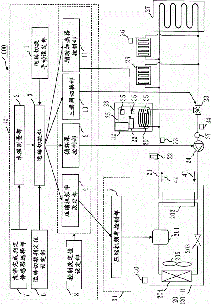
[0042] use figure 1Heat pump hot water supply system 1000 according to Embodiment 1 will be described. figure 1 The heat pump hot water supply system 1000 relative to Figure 17 The shown conventional heat pump hot water supply system includes a heat source machine controller 31 and a system controller 32 (hot water supply system control device). In addition, as a constituent element, with respect to Figure 17 The conventional heat pump hot water supply system shown also has one or more tank water temperature sensors 35 (tank water temperature detection sensors), outside air temperature sensors 30, supply hot water temperature sensors 33 (second refrigerant temperature detection sensors) One example), return hot water temperature sensor 34 (an example of second refrigerant temperature detection sensor), room temperature sensor 36 , sensor group such as flow sensor 37 , and auxiliary heat source 22 . When the rotation speed of the circulation pump is fixed, the flow sensor ...
Embodiment approach 2
[0130] Figure 8 It is a block diagram of the system controller 32 in Embodiment 2. The system controller 32 according to Embodiment 2 is characterized by further including a high-COP operating frequency calculation unit 12 . In the system controller 32 according to Embodiment 2, the operation switching unit 3 and the high-COP operating frequency calculation unit 12 constitute an operation control unit.
[0131] (High COP operating frequency calculation unit 12)
[0132] The high-COP operating frequency calculation unit 12 stores, for each frequency of the compressor 201, Figure 4 to Figure 6 The characteristic data group shown. For example, when the high-COP operating frequency calculation unit 12 is provided with the return hot water temperature as an input, the Figure 4~6 The approximate expression of the characteristic data shown (an example of correspondence information) calculates the operating frequency at which the COP is the highest.
[0133] Alternatively, the...
Embodiment approach 3
[0137] Figure 9 This is the operating method of the heat pump hot water supply system in the third embodiment. The system controller 32 further includes the boiling time estimation part 13 compared with the structure of Embodiment 2. The boiling time estimation part 13 estimates the boiling time to tank target water temperature. In the system controller 32 according to Embodiment 3, the operation switching unit 3 and the boiling time estimation unit 13 constitute an operation control unit.
[0138] Figure 10 It is a figure for demonstrating the primary delay characteristic in Embodiment 3. Regarding the water temperature change of the tank, such as Figure 10 As shown, roughly shows the characteristics of wasted time and one delay.
[0139] The time constant can be obtained by calculating the boiling time when it is assumed that a constant heat supply operation (an example of the boiling time estimation operation) is performed to keep the temperature difference and flow...
PUM
 Abstract
Description
Claims
Application Information
 - R&D Engineer
- R&D Manager
- IP Professional
- Industry Leading Data Capabilities
- Powerful AI technology
- Patent DNA Extraction
Browse by: Latest US Patents, China's latest patents, Technical Efficacy Thesaurus, Application Domain, Technology Topic, Popular Technical Reports.
© 2024 PatSnap. All rights reserved.Legal|Privacy policy|Modern Slavery Act Transparency Statement|Sitemap|About US| Contact US: help@patsnap.com