Device for testing gas flow field structure of kerf in laser cutting process

A test device and laser cutting technology, applied in the field of laser processing, can solve the problems of drastic changes in gas flow field structure and difficult detection

Inactive Publication Date: 2013-01-23
SHANGHAI JIAO TONG UNIV
View PDF4 Cites 0 Cited by
  • Summary
  • Abstract
  • Description
  • Claims
  • Application Information

AI Technical Summary

Problems solved by technology

Due to a large number of phenomena such as luminescence, heat generation and chemical reactions during the laser cutting process, the structure of the gas flow field in the slit changes drastically and is not easy to detect directly

Method used


Image

  • Device for testing gas flow field structure of kerf in laser cutting process
  • Device for testing gas flow field structure of kerf in laser cutting process

Examples


Embodiment Construction

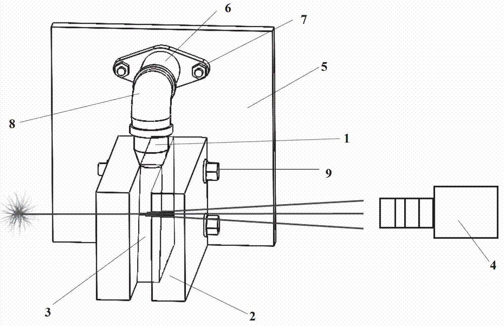
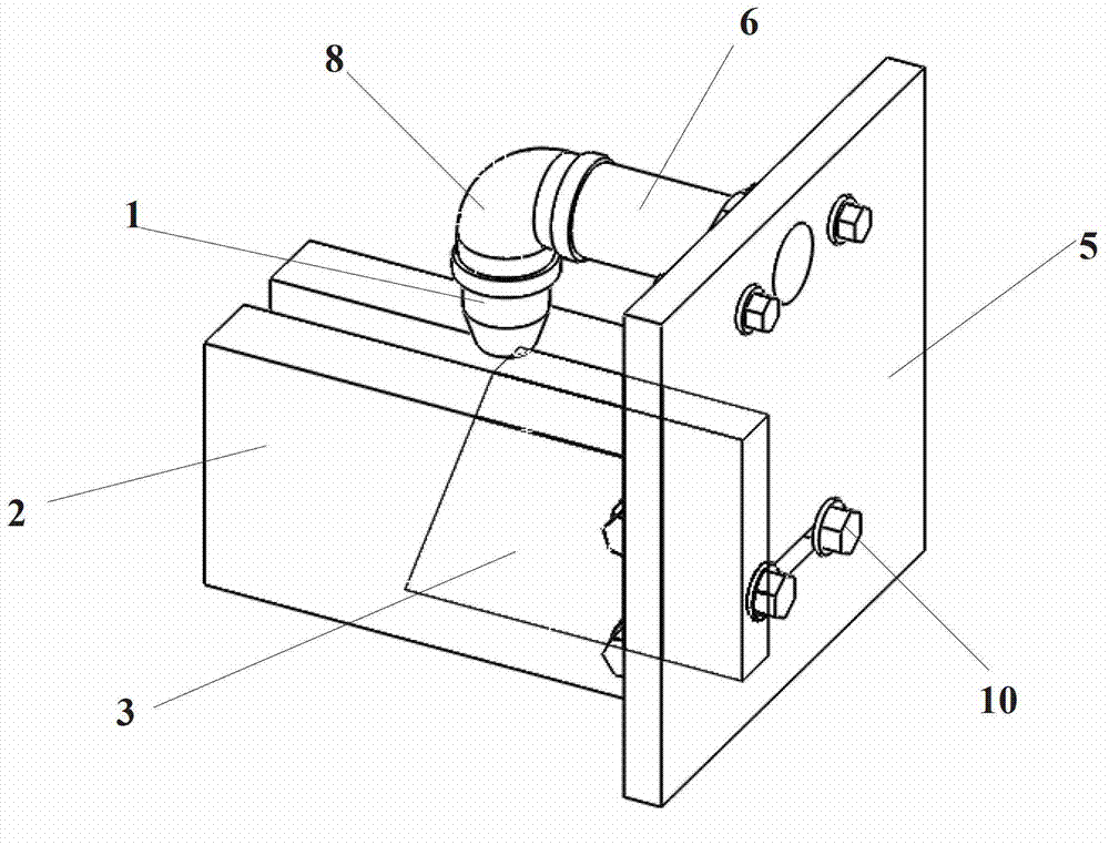
[0022] The present invention will be further described below in conjunction with the drawings and specific embodiments:

[0023] Such as figure 1 with figure 2 , A testing device for the gas flow field structure of slitting in the laser cutting process, including: a gas injection module with a nozzle 1, two pieces of plexiglass arranged in parallel 2, a thin metal plate with a bevel 3, a CCD camera 4, Support plate 5; the inner walls of the two opposing sides of the organic glass 2 are coated with viscous fluid.

[0024] Wherein, the beveled metal sheet 3 is fixed between the opposite surfaces of two pieces of organic glass 2; the two pieces of organic glass 2 and the gas injection module are fixed on the supporting plate 5; the nozzle 1 is located on the two pieces of organic glass. The top of the glass corresponds to the oblique angle of the thin metal plate 3. The CCD camera 4 is located on the outside of any organic glass and is arranged in parallel with the organic glass.

...


PUM


Abstract

The invention discloses a device for testing a gas flow field structure of a kerf in a laser cutting process. The device comprises a gas injection module with a nozzle, two pieces of organic glass which are opposite, a metal thin plate with an inclined angle, a charge coupled device (CCD) camera and a supporting plate, wherein viscous fluids are respectively coated on the inner walls of opposite surfaces of the two pieces of organic glass; the metal thin plate with the inclined angle is fixed between the opposite surfaces of the two pieces of organic glass; the two pieces of organic glass and the gas injection module are fixed on the supporting plate; the nozzle is arranged above the two pieces of organic glass; and the CCD camera is positioned outside any organic glass and parallel to the organic glass. Compared with the prior art, the device has the advantages that by observing a supersonic speed gas flow field in the kerf, the gas flow field structure can be obtained, key influencing factors of the gas flow field can be discovered through experiments on relevant process parameters, and experiment basis is provided for mechanism research of a laser cutting process.

Description

Technical field [0001] The invention relates to a test device, specifically, a device for observing the gas flow field structure in a slit in a laser cutting process, and belongs to the laser processing field in mechanical engineering. Background technique [0002] Laser cutting technology is widely used in automotive, sheet metal, aerospace and other fields, and is an important sheet metal processing technology. During the laser cutting process, the laser cutting head is perpendicular to the plate and emits laser light. The gas nozzle coaxial with the laser cutting head sprays auxiliary gas, and both act on the plate at the same time. The plate is heated and melted under the action of the laser, and the molten metal is blown out of the slit under the action of the auxiliary gas. With the movement of the laser head, the required shape is finally processed on the plate. [0003] The gas flow field structure in the slit has a great influence on the formation efficiency and the fina...

Claims


Application Information

Patent Timeline
Patent Type & Authority Applications(China)
IPC IPC(8): G01M10/00
Inventor 胡俊邱宪琛陈乐
Owner SHANGHAI JIAO TONG UNIV
Why Eureka
Try Eureka