Maintenance crane for electric full-variable frequency rock crushing station

A technology for crushing stations and cranes, applied in cranes, load hanging components, transportation and packaging, etc., can solve the problems of increased luffing power, high price, and large luffing thrust of oil cylinders, so as to reduce luffing power and improve work efficiency. Efficiency, low power consumption, variable amplitude effect

Inactive Publication Date: 2013-01-23
ELEPHANT KING HEAVY IND
View PDF8 Cites 6 Cited by
  • Summary
  • Abstract
  • Description
  • Claims
  • Application Information

AI Technical Summary

Problems solved by technology

[0005] 1. The pitch and amplitude of the boom is realized by the oil cylinder. The fulcrum of the oil cylinder is in the middle of the boom. Since the load of the boom is at the top, the boom is a cantilever beam structure, which bears a large force and the weight of the boom is heavy.
[0006] 2. Since the fulcrum of the oil cylinder to the jib is in the middle of the boom, the force arm of the oil cylinder to the lower hinge point of the jib is smaller than the force arm of the load to the lower hinge point, resulting in a larger luffing thrust of the oil cylinder and an increase in the luffing power. Medium energy consumption is more
[0007] 3. All the driving mechanisms of the crane are driven by hydraulic pressure, and the parts are all imported parts, which are expensive, and the maintenance cost of replacing parts and antifreeze hydraulic oil is high, and the maintenance technology of the hydraulic system is relatively difficult

Method used


Image

  • Maintenance crane for electric full-variable frequency rock crushing station
  • Maintenance crane for electric full-variable frequency rock crushing station
  • Maintenance crane for electric full-variable frequency rock crushing station

Examples


Embodiment Construction

[0031] The present invention will be further described below in conjunction with the accompanying drawings and specific embodiments.

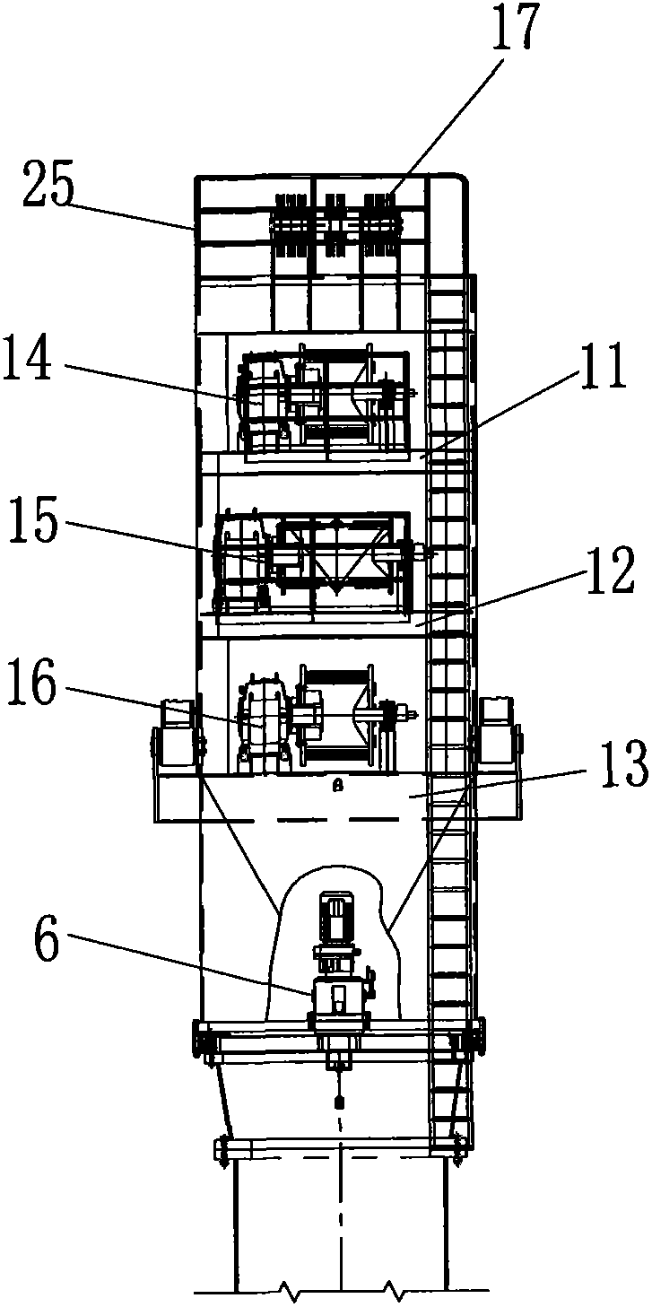
[0032] Such as figure 1 , image 3 The electric full frequency conversion rock crushing station maintenance crane shown in , includes an upper rotating column 1, and the bottom end of the arm frame 2 is hinged on the rotating shaft seat 3 fixed on the upper rotating column 1. The bottom of the upper rotating column 1 is connected with the connecting flange 5 through the slewing bearing 4 with high-strength bolts. The slewing bearing 4 in this embodiment is a roller-type slewing bearing with three rows. A rotary mechanism 6 for driving the internal teeth of the rotary bearing is fixed in the bottom of the upper rotary column 1 . The rotary mechanism 6 includes a motor 7, such as image 3 As shown in , the motor shaft is connected to the reducer 8, and a pinion 9 is arranged on the reducer shaft, and the pinion 9 meshes with the large internal...


PUM


Abstract

The invention relates to a maintenance crane for an electric full-variable speed rock crushing station. The maintenance crane comprises an upper rotary column, the bottom end of an arm frame is hinged on a rotating shaft seat, and the maintenance crane is characterized in that the upper rotary column and a connecting flange are connected together through a rotary support, and a slewing mechanism is fixedly arranged in the bottom of the upper rotary column. The slewing mechanism comprises a motor, a speed redactor and a small gear, wherein the small gear is meshed with a big gear of the rotary support. A platform is arranged at the middle part of the upper rotary column, and a winch is arranged on the platform. Pulley blocks are arranged at the top end of the upper rotary column and the top end of the arm frame, one end of a variable-amplitude steel wire rope is wound on a variable-amplitude winch, and the other end of the variable-amplitude steel wire rope is fixed at the top end of the upper rotary column. One end of a main hook steel wire rope is wound on a main lifting winch, and the other end of the main hook steel wire rope is fixed at the top end of the arm frame. One end of an auxiliary hook steel wire rope is wound on an auxiliary lifting winch, and the other end of the auxiliary hook steel wire rope is fixed at the top end of the arm frame. A main hook is hung on the main hook steel wire rope, and an auxiliary hook is hung on the auxiliary hook steel wire rope. The maintenance crane for the rock crushing station can save energy consumption and reduce cost.

Description

technical field [0001] The invention specifically relates to a crane, in particular to an electric full frequency conversion rock crushing station maintenance crane. Background technique [0002] The rock crushing station maintenance crane is used to lift out the crushing hammer that needs to be repaired in the crushing station, so as to facilitate its maintenance. The rock crushing station maintenance crane in the prior art is a fully hydraulic rock crushing station maintenance crane. It is composed of hydraulic winch, hydraulic slewing mechanism, main hook, auxiliary hook and other components. The main feature is that the mechanism drive is fully hydraulic drive. [0003] The pitching and luffing action of the crane jib is realized by the expansion and contraction of the luffing cylinder, and the two ends of the luffing cylinder are respectively hinged on the cylindrical column and the middle of the jib. The main lifting hydraulic winch drives the main hook up and down, ...

Claims


Application Information

Patent Timeline
Patent Type & Authority Applications(China)
IPC IPC(8): B66C23/06B66C23/16B66C23/84B66C13/16
Inventor 何先凡陈锁张艳丽
Owner ELEPHANT KING HEAVY IND
Why Eureka
Try Eureka