
Central hole punching device

A technology for drilling center holes and central shafts, which is applied to boring/drilling devices, drilling/drilling equipment, parts of boring machines/drilling machines, etc. It can solve the problems of simultaneous processing efficiency and low processing accuracy, and achieve convenient operation, Effect of cost reduction and cost reduction

Inactive Publication Date: 2013-01-23
山东白马永诚数控机床股份有限公司
View PDF4 Cites 0 Cited by
  • Summary
  • Abstract
  • Description
  • Claims
  • Application Information

AI Technical Summary

Problems solved by technology

For example, installing a center drill on the tool holder will occupy a tool position. When there are many processing tools, there may be no tool positions. This processing method requires time for tool change, and other parts cannot be processed at the same time when drilling. Therefore, the processing efficiency is low, and the processing accuracy is not high, because the center precision of the tool holder is generally 0.01mm

Method used


Image

  • Central hole punching device

Examples


Embodiment Construction

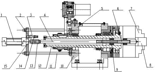
[0012] As shown in the figure, this embodiment includes a spindle assembly 5 , and the front end of the spindle assembly fixes a workpiece 8 through a chuck 7 . The main shaft assembly 5 has its main shaft seat 10 and the central shaft 12 installed on the main shaft seat 10 by bearings. In this embodiment, the central shaft 12 is a tubular structure, and its inner cavity is equipped with a push rod 4 through the support member 9. The support member 9 is fixedly connected with the inner cavity of the central shaft 12, and the push rod 4 and the support member 9 are dynamically matched. , The front end of the push rod 4 is provided with a mounting mechanism for the center drill 12 . At the rear end of the main shaft seat 10, a coupling plate 2 is installed through a set of pull rods 11, and the push cylinder 1 is fixed on the rear side of the coupling plate 2. The rear end of the push cylinder 1 is connected, and the piston rod and the ejector rod 4 of the cylinder 1 are respec...


PUM


Abstract

The invention relates to a mechanical working device, in particular to a central hole punching device. The central hole punching device is provided with a main shaft assembly comprising a main shaft seat and a central shaft. The central hole punching device is characterized in that the central shaft adopts a tubular structure, and a push rod of which one end is used for installing a center drill is arranged in the tube cavity of the central shaft in a penetrating mode; the push rod is movably matched with the central shaft, and the rear end of the push rod is connected with a piston rod with a push air cylinder; and the push air cylinder is fixedly connected with the main shaft seat. The central hole punching device can punching while a machine tool processes parts, the situation that two sets of mechanisms are adopted in the past is simplified, the cost is reduced, and the operation is convenient. In addition, as the mechanical working device is manufactured on the basis of the existing equipment, the needed cost of improving the existing equipment can be greatly reduced, and production enterprises are beneficial to reform the existing equipment.

Description

technical field [0001] The invention relates to a machining device, in particular to a center hole drilling device. Background technique [0002] In lathe processing, some parts need to drill a center hole for positioning or tightening in the next process. The conventional processing method is to install a center drill on the tool holder, which will have some inevitable shortcomings. For example, installing a center drill on the tool holder will occupy a tool position. When there are many processing tools, there may be no tool positions. This processing method requires time for tool change, and other parts cannot be processed at the same time when drilling. Therefore, the processing efficiency is low, and the processing accuracy is not high, because the center precision of the tool holder is generally 0.01mm. Contents of the invention [0003] The object of the present invention is to disclose a center hole punching device capable of centering a part when the part is proc...

Claims


Application Information

Patent Timeline
Patent Type & Authority Applications(China)
IPC IPC(8): B23B43/00B23B47/22
Inventor 林高波
Owner 山东白马永诚数控机床股份有限公司
Learn More