Throttling liquid feeding refrigerating system with jet pump

A technology of refrigeration system and jet pump, which is used in refrigerators, refrigeration and liquefaction, lighting and heating equipment, etc., to achieve the effect of simple structure, avoiding waste and reducing flow resistance

Active Publication Date: 2015-03-11
SHANGHAI OCEAN UNIV
View PDF6 Cites 3 Cited by
  • Summary
  • Abstract
  • Description
  • Claims
  • Application Information

AI Technical Summary

Problems solved by technology

But there is no report about a jet pump throttling liquid supply refrigeration system

Method used


Image

  • Throttling liquid feeding refrigerating system with jet pump
  • Throttling liquid feeding refrigerating system with jet pump
  • Throttling liquid feeding refrigerating system with jet pump

Examples


Embodiment 1

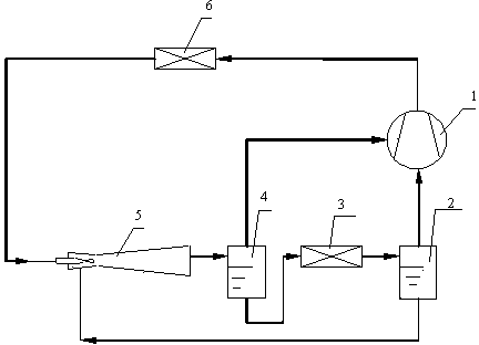
[0023] Please refer to the attached figure 2 , with figure 2 It is a schematic diagram of the jet pump throttling liquid supply refrigeration system of the present invention, and the jet pump throttling liquid supply refrigeration system includes a compressor 1, a condenser 6, a jet pump 5, a vapor-liquid separation liquid supply barrel 4, and an evaporator 3 and the vapor-liquid separation circulation barrel 2, the outlet of the compressor 1 is connected to the inlet of the condenser 6, the outlet of the condenser 6 is connected to the nozzle inlet of the jet pump 5, and the suction port of the jet pump 5 is connected to the steam The liquid outlet of the liquid separation circulation barrel 2 is connected, the discharge port of the jet pump 5 is connected with the inlet of the vapor-liquid separation liquid supply barrel 4, and the gas outlet of the vapor-liquid separation liquid supply barrel 4 is connected with the intermediate suction of the compressor 1 port connectio...

Embodiment 2

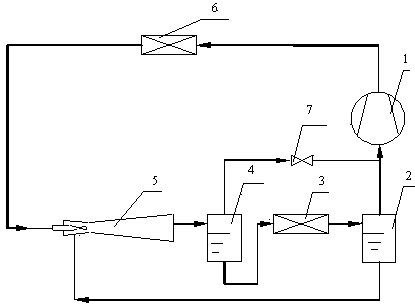
[0028] Please refer to the attached image 3 And attached Figure 5 , with image 3 It is a schematic diagram of the jet pump throttling liquid supply refrigeration system of the present invention (the compressor has no intermediate steam suction port), and the attached Figure 5 It is the pressure-enthalpy diagram of the refrigeration cycle of the jet pump throttling liquid supply refrigeration system (the compressor has no intermediate suction port) of the present invention. Similar to Embodiment 1, the jet pump throttling liquid supply refrigeration system includes a compressor 1, a condenser 6, a jet pump 5, a vapor-liquid separation liquid supply barrel 4, an evaporator 3 and a vapor-liquid separation circulation barrel 2, and The difference in Embodiment 1 is that the compressor 1 does not have an intermediate suction port, the refrigerant vapor (k) from the vapor-liquid separation liquid supply barrel 4 is depressurized (b) through the valve 7, and is separated from t...


PUM


Abstract

The invention relates to a throttling liquid feeding refrigerating system with a jet pump. The throttling liquid feeding refrigerating system comprises a compressor, a condenser, the jet pump, an evaporator, a vapor-liquid separation circulating barrel and a vapor-liquid separation liquid feeding barrel. Vapor in two-phase refrigerant flow from the inside of the jet pump is fed back to the compressor via a middle vapor sucking port of the compressor by the aid of the vapor-liquid separation liquid feeding barrel, so that liquid in the two-phase refrigerant flow from the inside of the jet pump is fed into the evaporator; and a vapor outlet of the vapor-liquid separation liquid feeding barrel is connected with the middle vapor sucking port of the compressor, and a liquid outlet of the vapor-liquid separation liquid feeding barrel is connected with an inlet of the evaporator. The throttling liquid feeding refrigerating system has the advantages that the return pressure of a part of the vapor of refrigerants can be increased, and the part of the vapor of the refrigerants can directly return to the compressor without flowing through the evaporator, so that operating efficiency of the refrigerating system is improved; the amount of the liquid fed to the evaporator of the system can be multiplied, a circulating liquid pump is omitted, and power consumption of the circulating liquid pump is saved; and the throttling liquid feeding refrigerating system can be used for various types of air conditioning, refrigerating and low-temperature systems, and the purpose of saving energy is achieved.

Description

technical field [0001] The invention relates to a refrigerating system, in particular to a jet pump throttling liquid supply refrigerating system which can be used in technical fields such as air conditioning, refrigeration and low temperature. Background technique [0002] The vapor compression refrigeration cycle is mainly composed of a compressor, a condenser, a throttling element and an evaporator. Among them, the throttling elements widely used mainly include capillary tubes and thermal expansion valves; The pump (usually a centrifugal pump) consumes electricity to increase the pressure of the throttled liquid refrigerant and then supplies it to the evaporator. [0003] In order to use the expansion work of the refrigerant throttling process, more and more researches on jet pumps (ejectors) are focused on using the expansion work to increase the pressure of the refrigerant gas entering the compressor. In 1983, Lorentzen, G proposed in the document "Throttling the inter...

Claims


Application Information

Patent Timeline
Patent Type & Authority Patents(China)
IPC IPC(8): F25B1/00
Inventor 万金庆宋立尧曹晓程赵彦峰李佳田晓雨蔡黎燕
Owner SHANGHAI OCEAN UNIV
Why Eureka
Try Eureka