
Surface defect detection line light source

A defect detection, line light source technology, applied in the direction of light source, electric light source, light source fixed, etc., to achieve uniform light brightness, expand the detection range, and ensure the effect of the detection effect

Active Publication Date: 2013-01-09
WAVE CREST SHANGHAI
View PDF5 Cites 6 Cited by
  • Summary
  • Abstract
  • Description
  • Claims
  • Application Information

AI Technical Summary

Problems solved by technology

The line light source can effectively solve the problems existing in the existing common light source

Method used


Image

  • Surface defect detection line light source
  • Surface defect detection line light source
  • Surface defect detection line light source

Examples


Embodiment Construction

[0028] In order to make the technical means, creative features, goals and effects achieved by the present invention easy to understand, the present invention will be further described below in conjunction with specific illustrations.

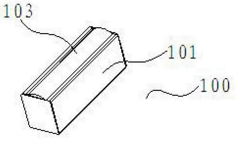
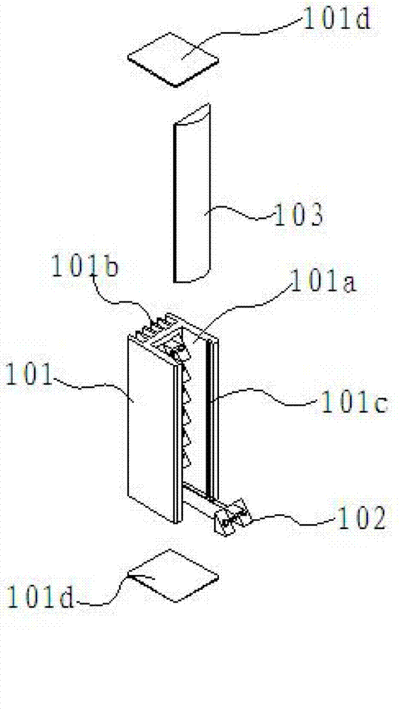
[0029] Depend on figure 1 and figure 2 It can be seen that the line light source 100 for surface defect detection provided by the present invention includes a base body 101 , a light source 102 and a convex lens 103 .

[0030] The base body 101 is the main body of the entire light source and is used to carry other components. It has a rectangular parallelepiped structure as a whole, and a light source installation groove 101a is defined in the middle along its extending direction.

[0031] Since the light source 102 needs to be installed in the base body 101 , it needs to have good heat dissipation. In the present invention, the seat body 101 is made of aluminum alloy as a whole, and the seat body 101 formed in this way not only has a good he...


PUM


Abstract

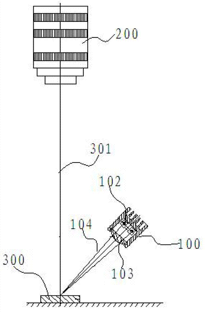
The invention discloses a surface defect detection line light source which comprises a seat body, a light-emitting diode (LED) luminous source and a cylindrical convex lens, wherein the seat body is provided with a luminous source mounting groove along an extension direction; the LED luminous source is obliquely arranged in the mounting groove and has a variable angle; and the cylindrical convex lens and a notch of the mounting groove are configured and the cylindrical convex lens is detachably arranged in the notch. According to the surface defect detection line light source, the detection effect can be effectively improved.

Description

technical field [0001] The invention relates to surface defect detection technology, in particular to a line light source used for surface defect detection. Background technique [0002] Defect detection usually refers to the detection of surface defects of objects. Surface defect detection uses advanced machine vision detection technology to detect defects such as spots, pits, scratches, color differences, and defects on the surface of workpieces. [0003] At present, in the entire production process of electronic production, SMT surface mount and other fields, it is necessary to carry out appearance quality inspection and quality control of the involved electronic components, patches, etc., and check whether the surface of components and patches is If there are defects such as foreign matter or scratches, the substandard components and patches are discharged in advance to avoid the waste of later rework. [0004] The light sources currently used are generally ordinary lig...

Claims


Application Information

Patent Timeline
IPC IPC(8): F21S8/00F21V19/00F21V29/00G01N21/88F21Y101/02F21V29/83F21V29/89
Inventor 邵幼平童雷
Owner WAVE CREST SHANGHAI
Learn More