
A deslagging device for thin oil lubricated bearing seat of decanter centrifuge

A decanter centrifuge, thin oil lubrication technology, applied in the direction of bearing components, shafts and bearings, rigid supports of bearing components, etc., can solve the problems of centrifuges such as harsh operating environment, bearing damage, and reduced service life of bearings, and achieve a large Promote the application value, improve the service life, and save the effect of bearing wear

Inactive Publication Date: 2016-03-30
SHANGHAI CENTRIFUGE INST
View PDF4 Cites 0 Cited by
  • Summary
  • Abstract
  • Description
  • Claims
  • Application Information

AI Technical Summary

Problems solved by technology

[0002] When the main bearing of the decanter centrifuge is lubricated with thin oil, the bearing can still be in a lubricated state under the condition of poor oil supply. This is because an oil storage ring is installed inside the bearing housing, but the bottom of the oil storage ring will gradually fade after a period of time. Accumulate impurities. When the impurities accumulate to a certain extent, they will rise and contact the bearing, which will damage the bearing and reduce the life of the bearing.
[0003] The existing countermeasure is to open the upper cover of the main bearing seat of the centrifuge, take out the main shaft, and remove the impurities accumulated in the oil storage ring when the centrifuge is undergoing minor repairs in about a year. There are two points for this situation: Disadvantages: ① The operating environment of the centrifuge itself is relatively harsh. After about one year of operation, the thickness of impurities stored in the oil storage ring has exceeded the outer ring of the bearing, causing certain damage to the bearing. Although this damage is not serious, it is often In the past, it will inevitably reduce the service life of the bearing, which will lead to a decrease in the performance of the centrifuge, and more seriously, the centrifuge will not work properly.
②The manufacturing precision of the Hough surface of the main bearing seat of the centrifuge is relatively high, and the increase in the number of openings of the bearing seat will inevitably affect the manufacturing accuracy of the Hough surface. Occurrence of oil spills
For the above problems, whether it is repair or replacement, it needs to stop work, affect work efficiency, and cause great economic losses. In addition, the economic loss of specific and direct parts modification and replacement is even greater. This field is eager to have a good technical solution to solve the problem. change, improve

Method used


Image

  • A deslagging device for thin oil lubricated bearing seat of decanter centrifuge
  • A deslagging device for thin oil lubricated bearing seat of decanter centrifuge
  • A deslagging device for thin oil lubricated bearing seat of decanter centrifuge

Examples


Embodiment Construction

[0026] The structure of the present invention will be further described in detail below in conjunction with the accompanying drawings.

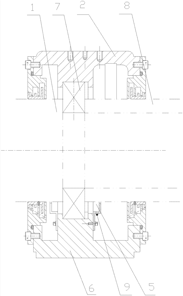
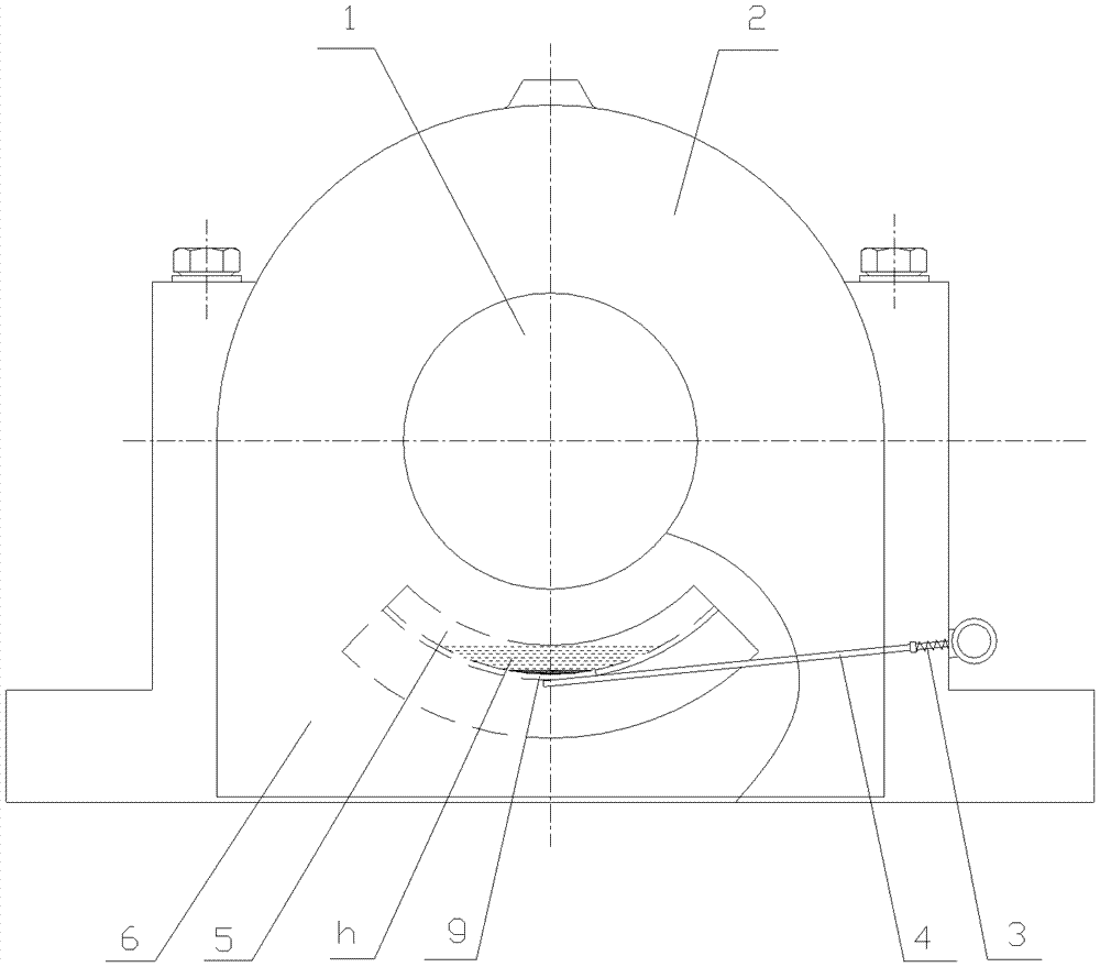
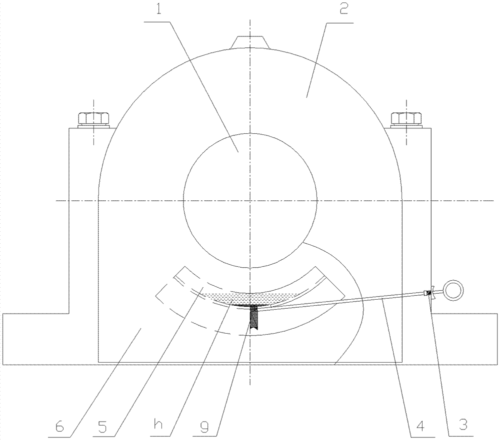
[0027] A deslagging device for a thin oil lubricated bearing seat of a decanter centrifuge. A crescent-shaped convex annular metal plate is fixed on the front and rear sides or both sides of the bearing seat to form an oil storage ring 5, and an oil storage ring 5 is provided at the bottom of the oil storage ring 5 The slag hole 9 is provided with a through hole 10 on the left or right side of the lower seat 6 of the bearing seat, and a metal rod 4 is arranged in the through hole 10. The metal rod 4 is a straight rod 4a and a ring at the end 4c; the ring 4c of the metal rod 4 is located outside the through hole 10, and the inner end of the straight rod 4a of the metal rod 4 is plugged at the bottom of the slag hole 9; A spring 3 is arranged between the protruding ring 4b and the circular ring 4c. The straight rod 4a of the metal rod 4, the pr...


PUM


Abstract

The invention relates to an improved structure of a part on a horizontal screw centrifuge, in particular to a residue removing device for a thin oil lubricating bearing seat of a horizontal screw centrifuge. A residue discharge hole (9) is arranged at the bottom of an oil storage ring (5). A through hole (10) is arranged in the left or right side part of a bearing seat lower seat (6). A metal bar (4) is configured in the through hole (10). The metal bar (4) consists of a straight bar (4a) and a circular ring (4c) at the end part. The circular ring (4c) of the metal bar (4) is arranged outside the through hole (10). The internal end of the straight bar (4a) of the metal bar (4) is padded at the bottom of the residue discharge hole (9). A protruding ring (4b) is arranged on the straight bar of the metal bar (4) at a position adjacent to the circular ring. A spring (3) is configured between the protruding ring (4b) and the circular ring (4c). The straight bar (4a) of the metal bar (4), the protruding ring (4b) and the spring (3) are all inserted into the through hole (10). One end of the spring (3) presses against the protruding ring (4b) and the other end of the spring (3) presses against the external side wall of the through hole (10). The residue removing device can remove impurities in the oil storage ring at any time, the impurities accumulated in the oil storage ring are prevented from overflowing out of the outer ring of a bearing and damaging the bearing, and the service life of the bearing is improved.

Description

technical field [0001] The invention relates to an improved structure of the upper part of a decanter centrifuge, in particular to an improved structure of a thin oil lubricated bearing seat of a decanter centrifuge. Background technique [0002] When the main bearing of the decanter centrifuge is lubricated with thin oil, the bearing can still be in a lubricated state under the condition of poor oil supply. This is because an oil storage ring is installed inside the bearing seat, but after a period of time, the bottom of the oil storage ring will gradually Accumulate impurities. When the impurities accumulate to a certain extent, they will rise, contact the bearing, damage the bearing, and reduce the life of the bearing. [0003] The existing countermeasure is to open the upper cover of the main bearing seat of the centrifuge, take out the main shaft, and remove the impurities accumulated in the oil storage ring when the centrifuge is undergoing minor repairs in about a yea...

Claims


Application Information

Patent Timeline
Patent Type & Authority Patents(China)
IPC IPC(8): F16C35/00F16C33/66
Inventor 周成蹊钱健航卢彦俊钱青
Owner SHANGHAI CENTRIFUGE INST
Learn More