Method and device for achieving sea wave energy transformation by using inertance
A technology of energy conversion and ocean waves, applied in ocean energy power generation, engine components, machines/engines, etc., can solve the problems of huge infrastructure, high construction cost, and difficulty, and achieve full energy utilization, low construction cost, and simple structure Effect
- Summary
- Abstract
- Description
- Claims
- Application Information
AI Technical Summary
Problems solved by technology
Method used
Image
Examples
Embodiment 1
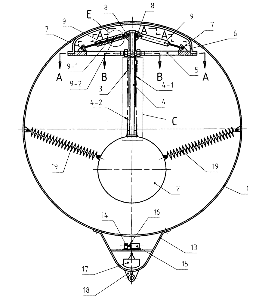
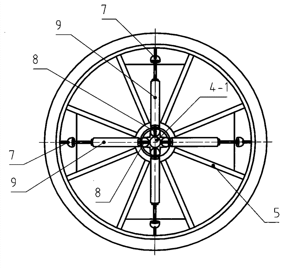
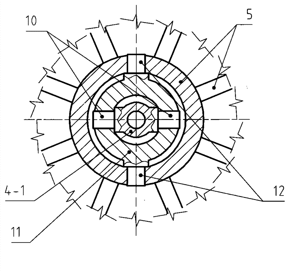
[0047] Example 1, such as Figure 1 ~ Figure 5 Shown.
[0048] in figure 1 Among them, 1 represents a carrying container; specifically, it is made into a sealed container. 2 represents an inertial body; specifically, it is made into a spherical weight. The inertial body 2 is suspended on the sleeve 4-1 of the shaft and sleeve assembly 4 through the spring 3; at the same time, the shaft 4-2 of the shaft and sleeve assembly 4 is also connected with the inertial body 2. When the carrying container 1 jolts up and down under the action of sea waves, there is a relative displacement between the sleeve 4-1 and the shaft 4-2 (the spring 3 is also stretched or compressed at this time). In order to make it easier to see its structure, the special general figure 1 The enlarged view of Part C in is drawn in Figure 4 in. In this embodiment, four springs 19 are also used to assist the positioning of the weight 2 (note: due to the shielding relationship, only two are shown in the figure). ...
Embodiment 2
[0056] Example 2, such as Figure 6 ~ Figure 8 Shown.
[0057] This embodiment is a partial change on the basis of embodiment 1:
[0058] 1. Inertial body 2 adopts spring 20 for full suspension; inertial body 2 adopts Image 6 , Figure 8 In addition to the sphere shown, a cube or other shapes can also be used.
[0059] 2. A conversion mechanism for converting relative movement into relative rotation is added to the shaft and sleeve assembly 21. Specifically, an annular rack segment 21-2-1 is formed on the shaft 21-2 of the shaft and sleeve assembly 21; an annular rack section 21-2-1 is installed on the sleeve 21-1 of the shaft and sleeve assembly 21 The gear 22 meshed with the rack section 21-2-1; then the rotation of the gear 22 is amplified by the speed increaser 23, and then the generator 24 generates electricity to complete the conversion of the energy from the waves into electric energy. Finally, the electricity generated by each power generation point can be collected and ou...
Embodiment 3
[0063] Example 3, such as Picture 9 Shown.
[0064] The most remarkable feature of this embodiment is that it has the form of a power generating ship. Picture 9 The hull 26 in the middle is equivalent to the carrying container 1 in the above embodiment. On the ship, or on the hull 26, a number of inertial bodies 2 are installed (note: only one is shown in the figure). Using the self-equipped drive system of the generator ship or equipped with a tug boat, the generator ship can be sent to the designated sea area and anchored and fixed, and then the power generation operation can be carried out.
[0065] The method and device for the installation of the inertial body 2 on the power generation ship, the method and device for transforming force and displacement, and the selection of the method and device for energy conversion can be adopted in addition to the methods and devices described in Embodiment 1 and Embodiment 2, as well as Other forms will not be repeated here.
[0066] Whe...
PUM
 Abstract
Description
Claims
Application Information
 - R&D
- Intellectual Property
- Life Sciences
- Materials
- Tech Scout
- Unparalleled Data Quality
- Higher Quality Content
- 60% Fewer Hallucinations
Browse by: Latest US Patents, China's latest patents, Technical Efficacy Thesaurus, Application Domain, Technology Topic, Popular Technical Reports.
© 2025 PatSnap. All rights reserved.Legal|Privacy policy|Modern Slavery Act Transparency Statement|Sitemap|About US| Contact US: help@patsnap.com


