
Retractable vortex generator

A vortex generator, low-speed technology, applied in the field of retractable vortex generators to improve the fluid dynamic characteristics of the flow above the hydrodynamic surface, can solve the problem of increasing the stall speed of the lifting surface, deteriorating low-speed performance, non-optimal flight conditions, etc. problem, to achieve the effect of improving low-speed performance

Active Publication Date: 2013-01-09
THE BOEING CO
View PDF6 Cites 11 Cited by
  • Summary
  • Abstract
  • Description
  • Claims
  • Application Information

AI Technical Summary

Problems solved by technology

Flow separation typically deteriorates low speed performance by causing boundary layer separation at high angles of attack
degraded low-speed performance in turn increases the "stall speed" of the lifting surface, and may result in suboptimal flight conditions when the lifting surface is operated at the low speeds associated with takeoff and approach to landing

Method used

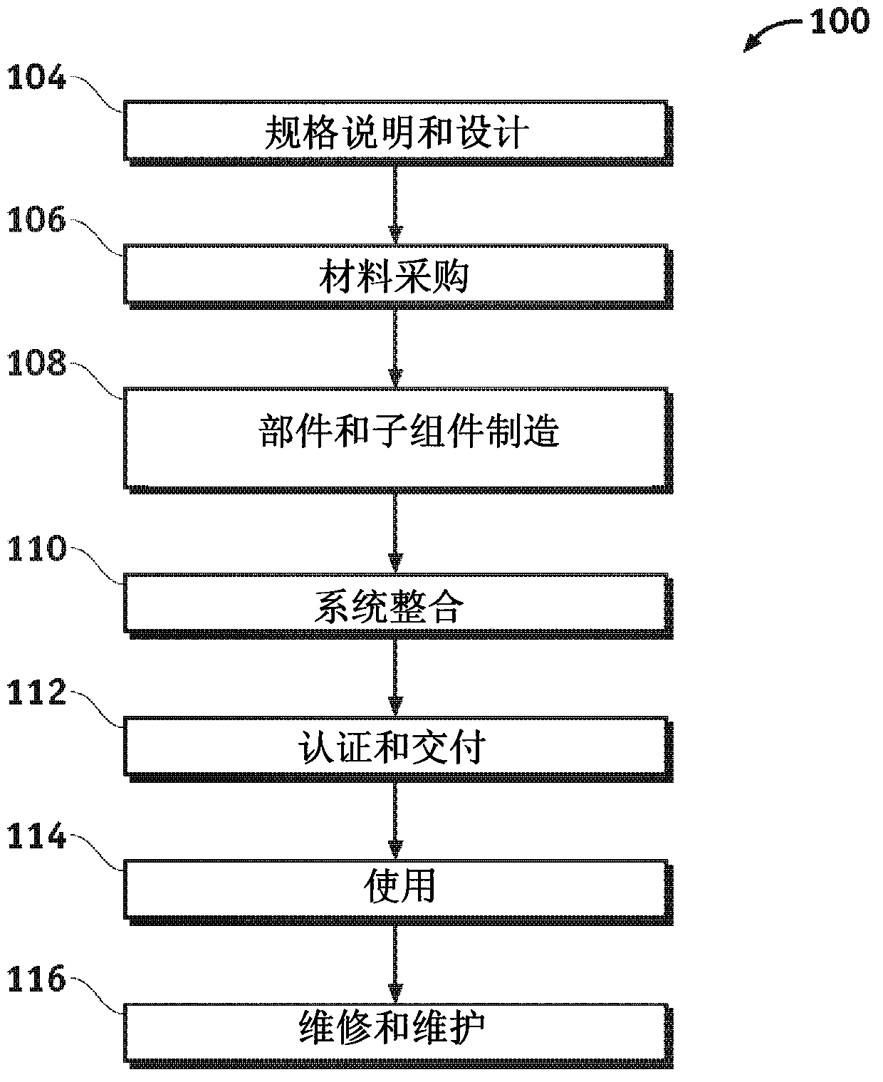
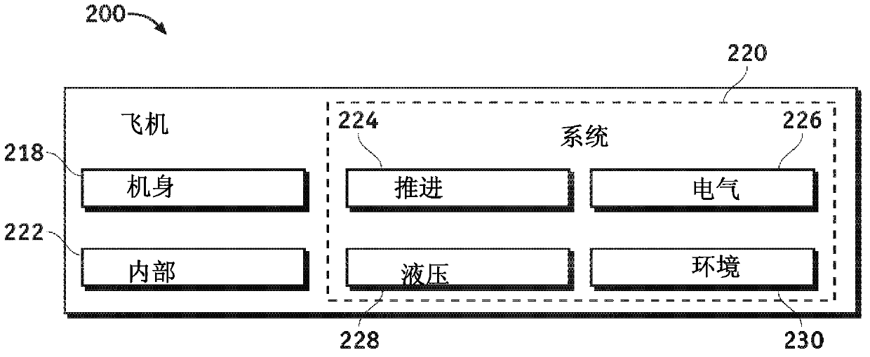
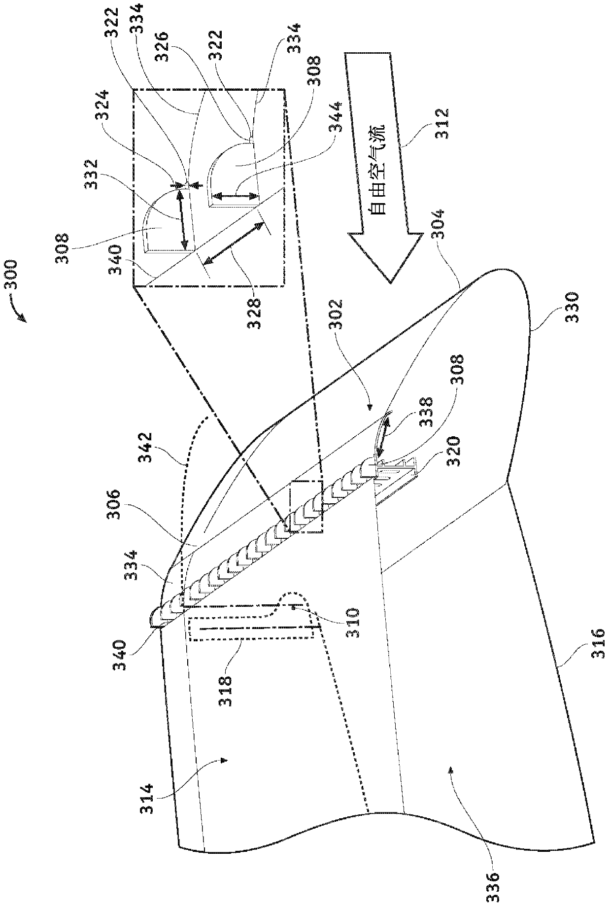

Image

  • Retractable vortex generator
  • Retractable vortex generator
  • Retractable vortex generator

Examples


Embodiment Construction

[0020] The following detailed description is exemplary in nature and is not intended to limit the invention or the application and uses of the embodiments of the invention. Descriptions of specific devices, techniques, and applications are provided as examples only. Modifications to the examples described herein will be readily apparent to those of ordinary skill in the art, and the general principles defined herein may be applied to other examples and applications without departing from the spirit and scope of the invention. Furthermore, there is no intention to be bound by any expressed or implied theory presented in the preceding technical field, background, brief summary or the following detailed description. The present invention should be accorded scope consistent with the claims and not limited to the examples described and shown herein.

[0021] Embodiments of the invention may be described herein in terms of functional and / or logical block components and various proc...


PUM


Abstract

A device and methods for low speed performance improvement of a lifting surface assembly (300) are disclosed. At least one vortex generator (308) is coupled to the lifting surface assembly, and the vortex generator is extended through the lifting surface assembly by drooping a hinged leading edge device (302) coupled to the lifting surface assembly to increase lift. The vortex generator is retracted inside the lifting surface assembly to decrease drag.

Description

technical field [0001] Embodiments of the invention generally relate to flow over a hydrodynamic surface. More specifically, embodiments of the present invention relate to retractable vortex generators for improving the hydrodynamic properties of flow over a hydrodynamic surface. Background technique [0002] Flow separation typically occurs when the boundary layer moves toward the leading edge of the lifting surface, and far enough away from the counterpressure gradient that the velocity of the boundary layer relative to the lifting surface drops to almost zero. The fluid flow separates from the lifting surface and then forms eddies and eddies instead. In aerodynamics, flow separation from time to time can lead to increased drag and decreased lift. Flow separation typically deteriorates low speed performance by causing boundary layer separation at high angles of attack. The degraded low speed performance in turn increases the "stall speed" of the lifting surface and may ...

Claims


Application Information

Patent Timeline
Patent Type & Authority Applications(China)
IPC IPC(8): B64C3/38
CPCY02T50/12Y02T50/162B64C2230/26B64C2003/148B64C9/24Y02T50/32B64C23/06Y02T50/10Y02T50/30F05B2240/3062B64C9/12
Inventor B·R·福克斯S·J·福克斯
Owner THE BOEING CO
Learn More