


Quick Research
Generate reliable direction feasibility study reports for your R&D in just a few steps.

Technical Q&A
Discover and master advanced knowledge NOW. Basics, ideas, possibilities, all at once.

Find Solutions
As an expert in R&D theories, this can generate solutions to your technical problems instantly.

Evaluate Feasibility
Analyze your overall solution with one click, know your potential R&D risks in advance.

Monitor Landscape
Get weekly tech updates, stay abreast of the latest tech innovations and key insights.
Hole drilling apparatus and method for cutting machine
The technology of a drilling device and drilling method, which is applied in the direction of metal processing, etc., can solve the problems of damage to air permeability, cutting damage, damage to softness, etc., and achieve the effects of preventing air leakage, preventing increase in resistance, and avoiding reduction in cutting accuracy
- Summary
- Abstract
- Description
- Claims
- Application Information
AI Technical Summary
Problems solved by technology
Method used
Image


Examples
Embodiment 1
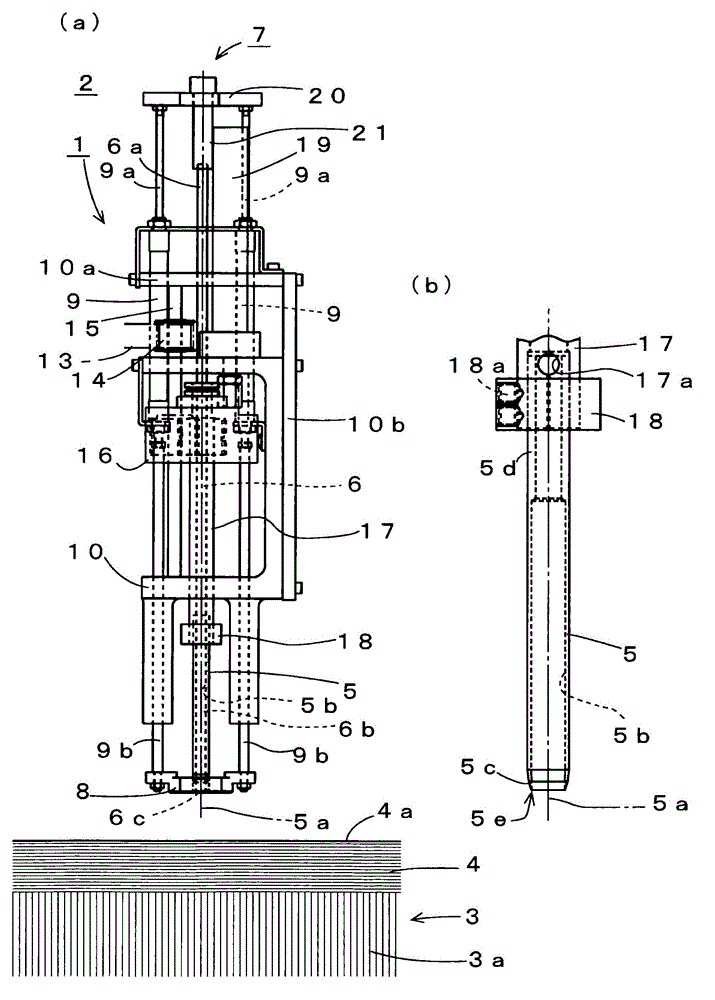
[0039] figure 1 and figure 2 The drilling device 1 shown in (a) is equipped with a cutting head that moves planarly along the surface of the cutting table 3 of the cutting machine 2 . Although illustration of the cutting head and the blade is omitted, the blade cuts the sheet materials 4 stacked on the cutting table 3 in accordance with preset cutting data. In order to hold the sheet material 4 in advance during cutting by the blade, the surface of the cutting table 3 is constituted by bristle brushes 3 a or the like. The bristle brush 3a has the flexibility to escape from the edge of the blade if the edge of the blade penetrates while maintaining air permeability for allowing the suction force from below to act. The surfaces of the laminated sheet materials 4 are covered with an air-impermeable film 4a. The drilling device 1 includes a hollow cylindrical rotary drill 5 for drilling.
[0040] figure 2 (b) shows the structure of the rotary drill 5 . The rotary drill 5 r...
Embodiment 2
[0056] Figure 7 , as another embodiment of the present invention, shows a structure in which a removing device 30 is provided near the surface of the sheet material 4 . The removal device 30 is built into a foot plate 31 that is driven up and down by the lower rod 9 b of the drive cylinder 9 . A suction hose 32 is connected to the foot pressure plate 31 . A discharge nozzle 33 is also provided on the foot pressure plate 31 , and compressed air is supplied through a discharge hose 34 . The cuttings 4 b pressed by the lower end 6 c of the pressing pin 6 in the foot press plate 31 so as to stay on the surface of the sheet material 4 can be moved to the suction hose 32 by blowing compressed air from the blowing nozzle 33 . , to remove by suction. If the suction force is large, the discharge nozzle 33 may not be provided. In addition, instead of using the structure on the suction side such as the suction hose 32, an outlet hole may be provided on the foot press plate 31, and o...
PUM
 Abstract
Description
Claims
Application Information
 - R&D Engineer
- R&D Manager
- IP Professional
- Industry Leading Data Capabilities
- Powerful AI technology
- Patent DNA Extraction
Browse by: Latest US Patents, China's latest patents, Technical Efficacy Thesaurus, Application Domain, Technology Topic, Popular Technical Reports.
© 2024 PatSnap. All rights reserved.Legal|Privacy policy|Modern Slavery Act Transparency Statement|Sitemap|About US| Contact US: help@patsnap.com