
Laser cutting and positioning tool

A positioning tooling and laser cutting technology, which is applied in laser welding equipment, welding/cutting auxiliary equipment, auxiliary devices, etc., can solve the problems of affecting processing quality, affecting processing speed, and cumbersome positioning methods, so as to achieve good cutting quality and save materials , Positioning convenient and quick effect

Inactive Publication Date: 2013-01-09
KUNSHAN JIZHICHENG MOLD
View PDF6 Cites 5 Cited by
  • Summary
  • Abstract
  • Description
  • Claims
  • Application Information

AI Technical Summary

Problems solved by technology

[0003] In order to solve the problem in the prior art that the positioning of the workpiece is cumbersome during cutting, which affects the processing speed, and the positioning accuracy is poor, which affects the processing quality, the present invention provides a laser cutting positioning tool that can quickly and accurately locate the workpiece

Method used


Image

  • Laser cutting and positioning tool
  • Laser cutting and positioning tool
  • Laser cutting and positioning tool

Examples


Embodiment Construction

[0014] The present invention will be further described below in conjunction with the accompanying drawings.

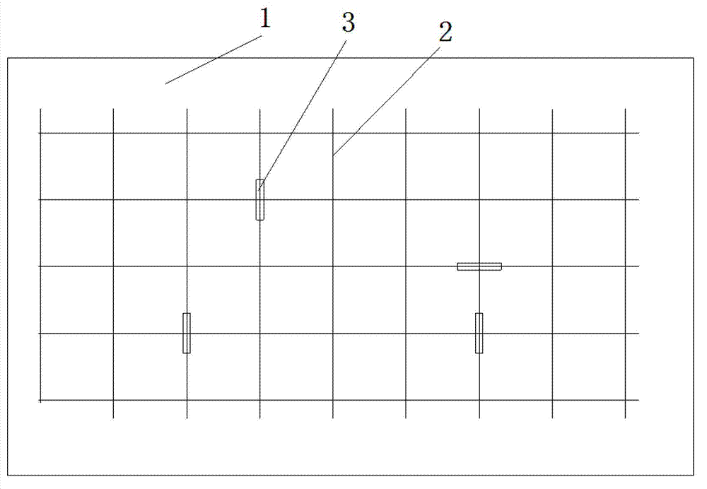
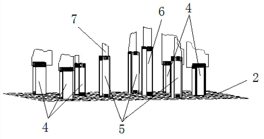
[0015] Such as Figure 1-2 As shown, a laser cutting positioning tool includes a workbench 1, unequal height support blocks 3 and symbol-shaped positioning brackets 7, and a rectangular grid line 2 is processed on the workbench 1, and the rectangular grid line 2 is composed of several hundred lines Connection composition. The unequal height support block 3 comprises five low support blocks 4, three middle support blocks 5 and a high support block 6, and according to the processing needs of the workpiece, the low support block 4, the middle support block 5 and the high support block 6 are set On the corresponding hundred lines, gaps are provided on these three support blocks, and screw holes are provided on both sides of the gap. Clamp and locate, then place the formed sheet on the symbol-shaped positioning bracket 7 for processing, after alignment, the program can be...


PUM


Abstract

The invention discloses a laser cutting and positioning tool, comprising a worktable. The laser cutting and positioning tool is characterized by further comprising a plurality of unequal-height supporting blocks and a mark-shaped positioning bracket, wherein rectangular grid lines are machined on the worktable; the unequal-height supporting blocks are arranged on the corresponding grid lines; clamping parts are arranged at the tops of the unequal-height supporting blocks; and the mark-shaped positioning bracket is placed at the clamping parts of the corresponding supporting blocks to be clamped and positioned. According to the laser cutting and positioning tool, the problems in the prior art that a positioning manner is complicated when a work piece is cut, the machining speed is influenced, the positioning precision is worse, and the machining quality is influenced are solved. The invention provides the laser cutting and positioning tool which can rapidly and accurately position the work piece and is suitable for all mould manufacturers and work piece manufacturing enterprises.

Description

technical field [0001] The invention belongs to the technical field of workpiece cutting, in particular to a laser cutting positioning tool. Background technique [0002] Laser technology has developed rapidly in recent years and has become a mainstream cutting technology. Because of its good cutting quality and precision, as well as unparalleled processing speed, the sheet metal industry generally believes that laser cutting is likely to replace stamping as the mainstream sheet metal processing technology in the future. Laser cutting is an expensive processing method. Among the currently known cutting processes, the cost of laser consumption is the highest, and the advantages of laser processing reflect high efficiency and high quality. Therefore, improving cutting efficiency and product quality is the key to reducing laser cutting. The most cost-effective tool for processing, and to achieve the above two points, fast, accurate and efficient positioning, clamping and align...

Claims


Application Information

Patent Timeline
Patent Type & Authority Applications(China)
IPC IPC(8): B23K26/42B23K26/38B23K26/70B23K37/04
Inventor 刘志泳
Owner KUNSHAN JIZHICHENG MOLD
Learn More