Pneumatic hammering demoulding mechanism

A demolding mechanism and a technology of a pneumatic hammer, which are applied in the field of horizontal continuous casting machines, can solve the problems of small stroke of hammer head movement, reduced hammer force, slow hammer head falling back, etc. Reliable, large contact area effect

Inactive Publication Date: 2014-09-03
JINAN JIGANG IRON ALLOY FACTORY
View PDF4 Cites 0 Cited by
  • Summary
  • Abstract
  • Description
  • Claims
  • Application Information

AI Technical Summary

Problems solved by technology

This demoulding mechanism is recorded in the invention patent CN201020567930. With this demoulding mechanism, the knocking force of the hammer head cannot be adjusted, so it cannot meet the needs of the knocking force caused by the change in the size of the cast alloy block; The change of the running speed of the continuous casting machine. When the running speed of the continuous casting machine is fast, the speed of retracting the cylinder is fast, and the falling speed of the hammer head under the action of its own weight is slow. When the cylinder is fully retracted, the hammer head and the hammer handle have not yet returned. When it reaches the lowest point, the air cylinder stretches out quickly, driving the hammer handle to hit the mold, the stroke of the hammer head is small, the vibration force generated is also small, and the demoulding effect is not good
When the running speed of the continuous casting machine is slow, when the cylinder is completely retracted, the hammer head and the hammer handle are swinging back and forth around the fulcrum. It is greatly reduced and cannot meet the needs of demoulding

Method used


Image

  • Pneumatic hammering demoulding mechanism
  • Pneumatic hammering demoulding mechanism
  • Pneumatic hammering demoulding mechanism

Examples


Embodiment Construction

[0022] The present invention will be further described below in conjunction with the accompanying drawings and embodiments.

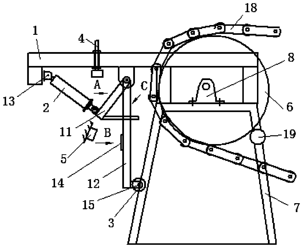
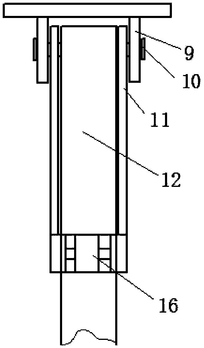
[0023] A pneumatic hammering demoulding mechanism, combined with Figure 1 to Figure 5 , including head support 7, demoulding support 1, cylinder 2, hammer head 3, movable arm 11, hammer handle 12, demoulding support 1 is connected with machine head support 7, and the end of demoulding support 1 is provided with second ear Seat 13, the second ear seat 13 is hingedly connected with the cylinder 2 tailstock, the middle part of the demoulding bracket 1 is provided with the first ear seat 9, the first ear seat 9 is provided with a shaft hole, and the first pin shaft is arranged in the shaft hole 10. The first lug 9 is hingedly connected to one end of the movable arm 11 and the hammer handle 12 respectively through the first pin shaft 10, and the other end of the hammer handle 12 is provided with a second pin shaft 15, and the hammer head 3 is passed through...


PUM


Abstract

The invention discloses a pneumatic hammering demoulding mechanism, which comprises a machine head support, a demoulding support, a cylinder, a hammer head, a movable arm and a hammer handle, the demoulding support is connected with the machine head support, and the end of the demoulding support is provided with a Two ear seats, the second ear seat is hingedly connected with the tailstock of the cylinder, the middle part of the demoulding bracket is provided with the first ear seat, and the first ear seat is respectively hinged with the movable arm and one end of the hammer handle through the first pin shaft, and the hammer head The second pin shaft is hinged to the hammer handle, and the other end of the movable arm is hinged to the outer end of the cylinder piston rod through the cylinder ear seat. Adjusting bolts are provided on the demoulding bracket, and an electromagnet is provided on the falling path of the hammer head. The iron is connected to the power supply through the proximity switch, the electromagnet is connected to the air control valve circuit, the air control valve is installed on the air circuit connected to the cylinder, and the proximity switch cooperates with the teeth of the sprocket. The structure is simple and practical, and the hammering force can be adjusted, which can adapt to the change of different speeds of the continuous casting machine, especially the demand of the hammering force when the continuous casting machine runs at a low speed.

Description

technical field [0001] The invention relates to the technical field of horizontal continuous casting machines, in particular to a pneumatic hammering demoulding mechanism. Background technique [0002] The demoulding mechanism of the current horizontal continuous casting machine: the casting mold is driven to rotate by the sprocket, and the sprocket is placed on the ingot casting machine bracket through the bearing seat, and there are alloy ingots in the casting mold; at the demoulding place of the horizontal continuous casting machine, that is, the head support The air hammer seat is fixed on the top, and the end of the air hammer seat is provided with a tailstock, which is connected to the tailstock of the cylinder with a direct pin; two ear climbers are fixed in front of the air hammer seat. , pass through with a shaft, and install an air hammer push block coaxially; the end of the cylinder and the air hammer push block are flexibly connected with a direct pin. This demo...

Claims


Application Information

Patent Timeline
Patent Type & Authority Patents(China)
IPC IPC(8): B22D11/045B22D29/06
Inventor 李明波王铮王茂周郭兴浩朱慧
Owner JINAN JIGANG IRON ALLOY FACTORY
Why Eureka
Try Eureka