
Apparatus and method for mixing of corrosive and non-corrosive gas

A mixing device, corrosive technology, used in the field of mixing devices for mixing two or more gases, can solve the problems of wear, expensive lining and coating

Inactive Publication Date: 2013-01-02
HALDOR TOPSOE AS
View PDF1 Cites 2 Cited by
  • Summary
  • Abstract
  • Description
  • Claims
  • Application Information

AI Technical Summary

Problems solved by technology

Liners and coatings can be expensive and will eventually wear out

Method used


Image

  • Apparatus and method for mixing of corrosive and non-corrosive gas
  • Apparatus and method for mixing of corrosive and non-corrosive gas
  • Apparatus and method for mixing of corrosive and non-corrosive gas

Examples


Embodiment Construction

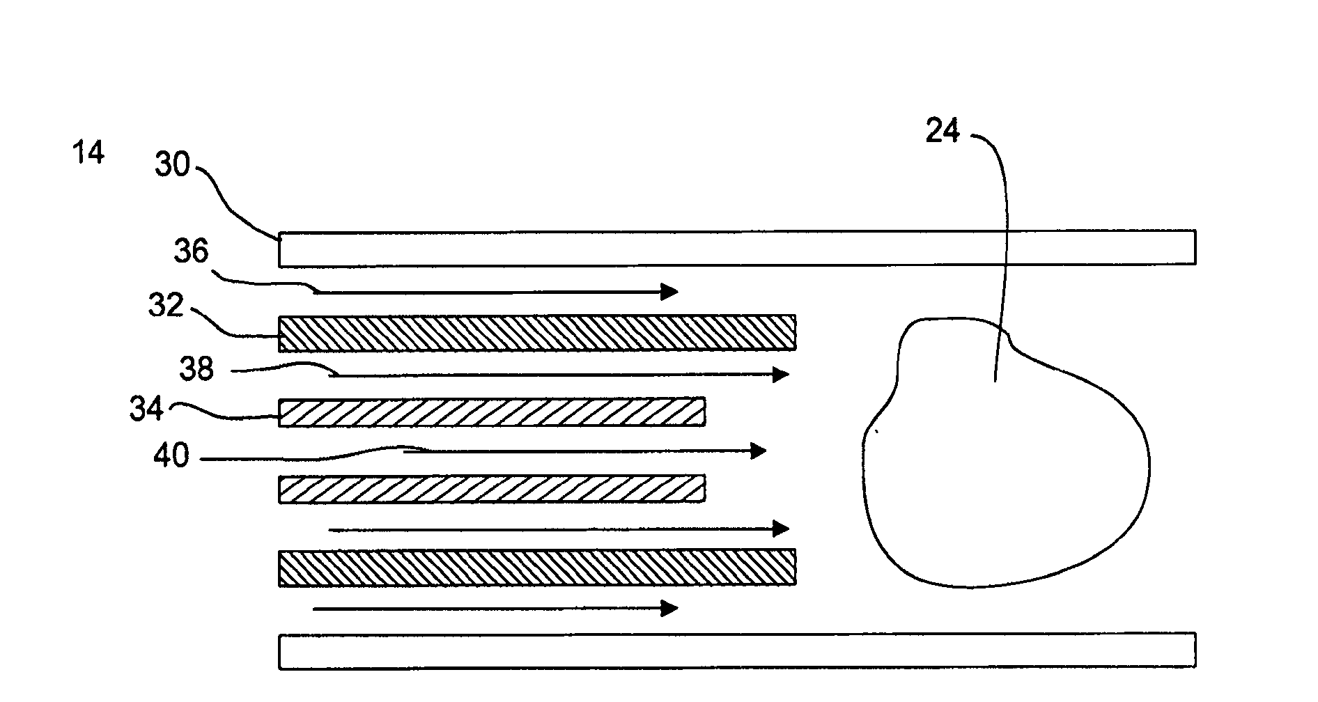
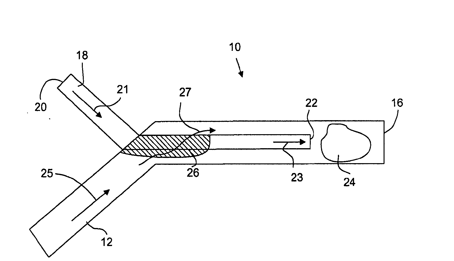
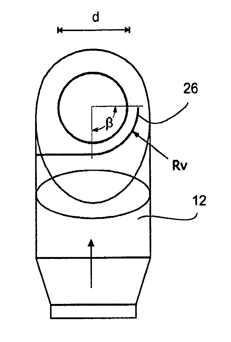
[0031] FIG. 1 schematically shows a mixing device 10 . The mixing device 10 is designed for mixing the first gas with the second gas. In a presently preferred embodiment, the device is used to mix two gases, one of which is corrosive to the mixing device. The mixing device 10 comprises a first gas guiding part 12 having a first gas guiding part inlet 14 and a first gas guiding part outlet 16 . The mixing device 10 also includes a second gas guiding part 18 having a second gas guiding part inlet 20 and a second gas guiding part outlet 22 . The second gas guiding part outlet 22 is arranged in the first gas guiding part 12 so as to mix the first gas and the second gas. A mixing zone is defined in the first gas guiding portion 12 . The mixing zone extends substantially from the area at the outlet 22 of the second gas guiding part. The size of the mixing zone 24 depends on the flow volume and velocity of the gas, and may also depend on the viscosity and temperature of the gas. ...


PUM


Abstract

Present application relates to a mixing device (10) for mixing a first gas with a second gas, the second gas being corrosive to the mixing device. The mixing device comprises a first gas guiding part (12) having a first gas guiding inlet part (14) and a first gas guiding outlet part (16), a second gas guiding part (18) having a second gas guiding inlet part (20) and a second gas guiding outlet part (22), the second gas guiding outlet part arranged in the first gas guiding part so that the first gas and the second gas are mixed and a guide vane configured to establish a swirling motion in the first gas. Further disclosed is a related method.

Description

technical field [0001] The invention relates to a mixing device. The invention also relates to a method for mixing. In particular, the invention relates to a mixing device for mixing two or more gases. The mixing unit can be part of a larger plant, such as a production plant. Background technique [0002] The mixing device needs to be protected when mixing at least one gas which is corrosive to the mixing device. This can be achieved by applying a lining or coating to the interior of the mixing device. Liners and coatings can be expensive and will eventually wear out. The present invention provides a device that overcomes at least these problems. Contents of the invention [0003] In a first aspect, the invention relates to a mixing device for mixing a first gas with a second gas, the second gas being corrosive to the mixing device, the mixing device comprising an end portion having a first gas guiding inlet portion and a first gas guiding part at the end of the firs...

Claims


Application Information

Patent Timeline
IPC IPC(8): B01F3/02B01F5/04B01F5/00B01F23/00B01F23/10B01F33/40
CPCB01F3/02B01F5/046B01F5/0453B01F5/0451B01F2005/0017B01F23/10B01F2025/913B01F25/3132B01F25/31324B01F25/3131B01F25/30B01F33/40
Inventor L.J.沙P.莫辛格S.海内森
Owner HALDOR TOPSOE AS
Learn More