A signal waveform conversion circuit

A technology for transforming circuits and signal waveforms, which is applied in the field of signal waveform transforming circuits, can solve the problems of reduced precision and long delay, and achieve the effect of solving the problem of reduced precision

Active Publication Date: 2015-12-16
BEIJING JINGWEI HIRAIN TECH CO INC
View PDF3 Cites 0 Cited by
  • Summary
  • Abstract
  • Description
  • Claims
  • Application Information

AI Technical Summary

Problems solved by technology

[0006] In view of this, the present invention provides a signal waveform conversion circuit to solve the problems of decreased precision and long delay

Method used


Image

  • A signal waveform conversion circuit
  • A signal waveform conversion circuit
  • A signal waveform conversion circuit

Examples


Embodiment Construction

[0048] The following will clearly and completely describe the technical solutions in the embodiments of the present invention with reference to the accompanying drawings in the embodiments of the present invention. Obviously, the described embodiments are only some of the embodiments of the present invention, not all of them. Based on the embodiments of the present invention, all other embodiments obtained by persons of ordinary skill in the art without making creative efforts belong to the protection scope of the present invention.

[0049] The invention provides a signal waveform conversion circuit to solve the problems of decreased precision and long time delay.

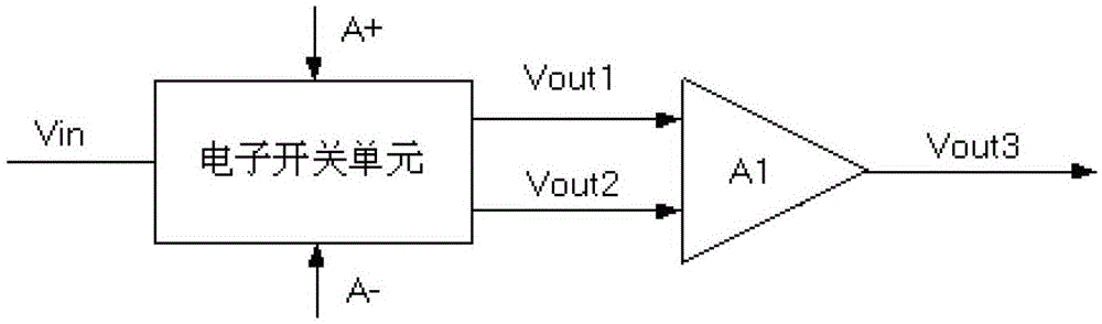
[0050] specific, image 3 As shown, including electronic switch unit and differential output unit, where:

[0051] The input terminal of the electronic switch unit is connected to the input signal Vin, and the output terminal is the first output signal Vout1 and the second output signal Vout2;

[0052]The input ...


PUM


Abstract

The invention provides a signal waveform converting circuit. The signal waveform converting circuit comprises an electronic switch unit and a differential motion output unit, wherein the electronic switch unit converts an input signal into two in-phase output signals, and the signal waveform converting circuit outputs a difference value between two in-phase output signals and converts the input signal into a direct current signal; as the input signal is not required to be converted into a steamed bread wave and then converted into the direct current signal, the problem of precision decrease caused by introducing of a diode when the input signal is converted into the steamed bread wave is solved, and the problem of long delay caused by introducing of a capacitor when the steamed bread wave is converted into a direct wave signal is solved.

Description

technical field [0001] The invention relates to the technical field of signal waveform conversion, in particular to a signal waveform conversion circuit. Background technique [0002] The signal waveform conversion circuit is a circuit used to convert the input signal of sine wave, triangle wave, square wave, etc. (or other waveforms, such as white noise signal, sawtooth wave, etc.) into another signal form. The existing waveform conversion circuit Such as figure 1 shown. [0003] Assuming that the input signal VIN is a sine wave, when the input signal VIN is greater than the reference voltage VREF, the diode D1 is cut off, and the diode D2 is turned on. At this time, the output signal Vout is figure 2 The graph of middle region I; when the input signal VIN is less than the reference voltage VREF, the diode D1 is turned on, and the diode D2 is cut off, the input signal VIN passes through the resistor R14 and the operational amplifier A2, and the output signal Vout is fi...

Claims


Application Information

Patent Timeline
Patent Type & Authority Patents(China)
IPC IPC(8): H03K5/22
Inventor 曹思飞米春晖
Owner BEIJING JINGWEI HIRAIN TECH CO INC
Why Eureka
Try Eureka