Stator manufacturing method, stator, and motor

A manufacturing method and stator technology, which are applied in the field of electric motors, can solve the problems of decreasing the occupancy rate and increasing the insulating parts, etc.

Inactive Publication Date: 2013-01-02
ASMO CO LTD
View PDF4 Cites 5 Cited by
  • Summary
  • Abstract
  • Description
  • Claims
  • Application Information

AI Technical Summary

Problems solved by technology

However, if the thickness of the insulating member is increased, the occupancy ratio may decrease

Method used


Image

  • Stator manufacturing method, stator, and motor
  • Stator manufacturing method, stator, and motor
  • Stator manufacturing method, stator, and motor

Examples


Embodiment Construction

[0028] One embodiment of the present invention will be described below with reference to the drawings.

[0029] Such as figure 1 As shown, the motor housing 2 of the motor 1 has: a cylindrical casing 3 formed in a bottomed cylindrical shape; figure 1 Middle left) the opening is closed. In addition, on the back side of the cylindrical case 3 ( figure 1 A circuit storage box 5 is installed on the end portion of the middle right side), and power circuits such as circuit boards are stored in the circuit storage box 5 .

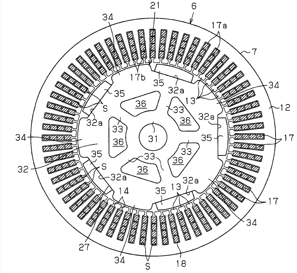
[0030] A stator 6 is fixed to the inner peripheral surface of the cylindrical case 3 . The stator 6 has an armature core 7 . The armature core 7 is formed by laminating a plurality of chips 11 . The chip 11 has a plate shape and is made of a steel plate. And, if figure 2 As shown, the armature core 7 has: an annular portion 12 formed in an annular shape; and a plurality of teeth 13 arranged in the circumferential direction. A plurality of teeth 13 respect...


PUM


Abstract

The invention provides a stator manufacturing method, a stator, and a motor which can ensure the insulation between a conductor and a armature core and can suppress the reducing of the fill-in ratio. The stator manufacturing method includes the steps of preparing an armature core, forming an insulating member including two opposing portions from a sheet-like insulating material, and deforming the insulating member to move the two opposing portions toward each other. The method also includes the step of inserting distal parts of the two opposing portions into the corresponding slit from the axial direction thereby covering an inner surface of each of the slot with the insulating member. Further, the method includes the steps of inserting a conductor forming a winding into each of the slots between the two opposing portions.

Description

technical field [0001] The present invention relates to a manufacturing method of a stator, a stator, and a motor including the stator. Background technique [0002] Conventionally, as a stator used in a motor, a stator including an SC winding (segment conductor winding) or the like has been proposed. As such a stator, there has been proposed a stator in which an insulating member is provided between a conductor constituting a winding and the armature core in order to ensure insulation between the conductor and the armature core. In addition, it is well known that a stator provided with SC windings can increase the occupation ratio of the windings. [0003] For example, the stator described in JP 2000-308314 A has a sheet-shaped insulating member. The armature core of this stator has a plurality of slots arranged in the circumferential direction, and a slit is formed radially inside each slot, and the circumferential width of the slit is narrower than the circumferential w...

Claims


Application Information

Patent Timeline
Patent Type & Authority Applications(China)
IPC IPC(8): H02K15/085H02K3/34H02K1/16
CPCH02K3/34H02K15/0018H02K15/085H02K1/16H02K21/14H02K1/278H02K3/12H02K15/10Y10T29/49009
Inventor 金原良将兼松康广
Owner ASMO CO LTD
Why Eureka
Try Eureka