Eureka AIR delivers breakthrough ideas for toughest innovation challenges, trusted by R&D personnel around the world.

Microporous metal cooling mirror and production method thereof

A metal cooling and microporous technology, applied in laser parts, electrical components, phonon exciters, etc., can solve the problems of difficult to ensure the heat dissipation capacity and surface shape of mirrors, difficult to control the distribution and size of micropores, etc., to achieve easy operation. , The method is simple, the effect of reducing the contact thermal resistance

Inactive Publication Date: 2013-01-02
HUAZHONG UNIV OF SCI & TECH
View PDF4 Cites 7 Cited by
  • Summary
  • Abstract
  • Description
  • Claims
  • Application Information

AI Technical Summary

Problems solved by technology

[0006] Microporous cooling mirrors (ZL201010201350.6) can be produced by laser sintering technology, but the distribution and size of the micropores produced by this method are difficult to control, making it difficult to guarantee the cooling capacity and surface shape of the mirror

Method used

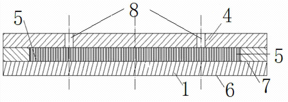
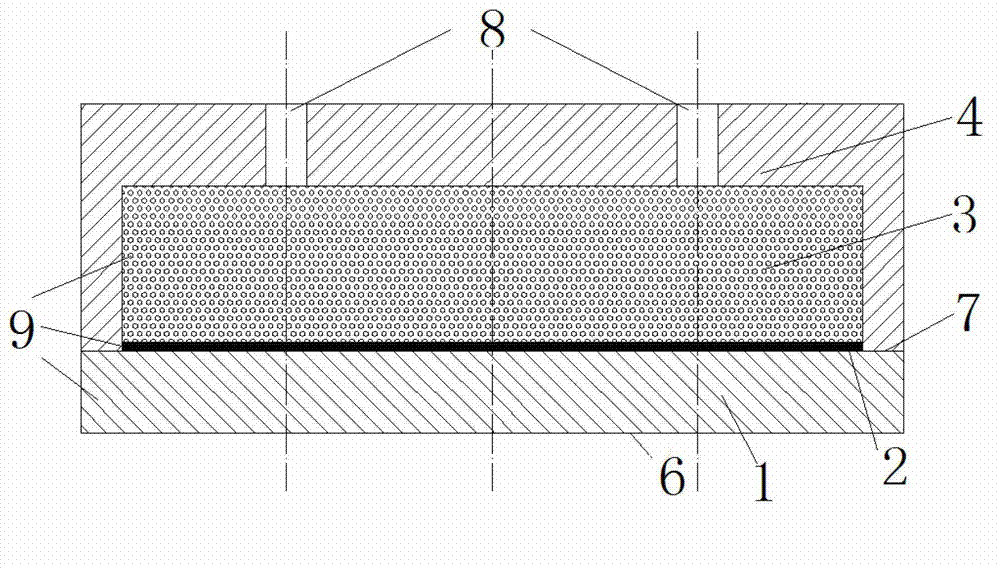
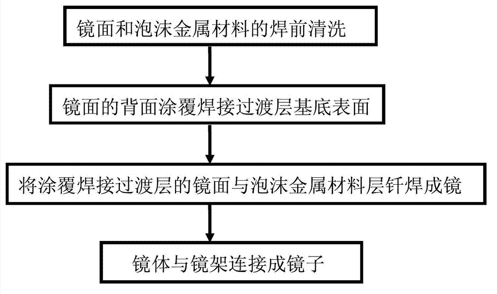

Image

  • Microporous metal cooling mirror and production method thereof
  • Microporous metal cooling mirror and production method thereof
  • Microporous metal cooling mirror and production method thereof

Examples


example 1

[0026] Example 1: Take foamed Cu as the foamed metal microporous layer material, and Si as the mirror surface material

[0027] Step 1: Clean the foamed Cu material with a pore size of 10 μm and a porosity of 95% and the Si mirror;

[0028] Step 2: plating a transition layer with a thickness of 500nm on Si, wherein the first layer is Cr with a thickness of 200nm, and the second layer is Ag with a thickness of 300nm;

[0029] Step 3: Brazing the Si coated with the transition layer and Cu foam to form a mirror body. The brazing temperature is 1000℃, and the welding time is 2h;

[0030] Step 4: Connect the welded mirror body and the mirror frame together with screws, and the connected mirror must not leak.

example 2

[0031] Example 2: Take foamed Cu as the foamed metal microporous layer material, and Mo as the mirror surface material

[0032] Step 1: cleaning foamed Cu and Mo with a pore size of 10mm and a porosity of 10%;

[0033] Step 2: There is no need to apply a transition layer due to the good wettability between Mo and Cu. The Mo mirror surface is brazed with foamed copper, the welding temperature is 1000°C, and the welding time is 5h;

[0034] Step 3: Connect the welded mirror body and mirror frame together with screws, and the connected mirror must not leak.

example 3

[0035] Example 3: Using Ni foam as the metal foam microporous layer material, W as the mirror surface material

[0036] Step 1: Clean the foamed Ni and W mirror surfaces with a pore size of 100 μm and a porosity of 60%;

[0037] Step 2: There is no need to apply a transition layer due to the good wettability between W and Ni. Weld the W mirror surface with the Ni foam, the welding temperature is 2000°C, and the welding time is 130h;

[0038] Step 3: Connect the welded mirror body and mirror frame together with screws, and the connected mirror must not leak.


PUM

PropertyMeasurementUnit
thicknessaaaaaaaaaa
porosityaaaaaaaaaa
porosityaaaaaaaaaa

Abstract

The invention discloses a microporous metal cooling mirror and a production method thereof. The cooling mirror comprises a mirror body and a mirror frame, wherein the mirror body comprises a mirror plate and a foam metal microporous layer which are integrally brazed; and the mirror frame comprises at least two liquid access passageways and is positioned behind the foam metal microporous layer to be tightly connected with the mirror body. The mirror plate and foam metal are directly brazed by adopting the brazing technology, so that cooling liquid can flow circularly in the foam metal; and therefore, the purposes of cooling the mirror plate and reducing the temperature rise and the deformation of the mirror plate are achieved. According to the invention, uniform and controllable microporous cooling layers are obtained on the mirror plate, so that large deformation of the mirror plate is inhibited and the problem that the foam metal and the mirror plate are difficult to weld during brazing is solved; and under the action of the capillary force, melted brazing filler metal is fed into the bottom layer of the foam metal suitably, so that the contact thermal contact resistance between the bottom layer of the foam metal and the base of the mirror plate is reduced. The brazing technology can be directly used for producing microporous metal cooling mirrors, so that the method is simple and the operation is easy.

Description

technical field [0001] The invention belongs to the field of laser optical resonant cavities, and in particular relates to a microporous metal cooling mirror and a manufacturing method thereof, which are mainly used for high-energy laser optical resonant cavities and optical chains with high requirements on high power density and surface shape. Background technique [0002] The laser optical resonator cavity mirror and the mirror in the optical chain absorb laser energy, resulting in a temperature rise of the mirror surface, resulting in a change in the surface shape of the mirror surface, causing distortion of the laser wavefront, and resulting in a decrease in the quality and stability of the output beam. As the laser power becomes higher and higher, this problem becomes more and more prominent. Therefore, reducing the thermal deformation of the mirror is a key technology in high-power laser technology. At present, there are three main ways to reduce the thermal distortio...

Claims


Application Information

Patent Timeline
Patent Type & Authority Applications(China)
IPC IPC(8): H01S3/042
Inventor 朱海红何崇文胡攀攀
Owner HUAZHONG UNIV OF SCI & TECH
Why Eureka
Eureka Blog
Learn More