
Land airship

A spaceship and tire technology, which is applied in the field of land spacecraft, can solve the problems of large space occupation, bulky size, and inability to adapt to water or sea driving, etc., and achieves the effects of strong applicability, small size, and good manufacturing flexibility

Active Publication Date: 2013-01-02
冯计成
View PDF6 Cites 22 Cited by
  • Summary
  • Abstract
  • Description
  • Claims
  • Application Information

AI Technical Summary

Problems solved by technology

However, this patent cannot be adapted to water or sea driving, and the air-and-land vehicle of this patent needs a rotor, which is bulky and takes up a lot of space

Method used


Image

  • Land airship
  • Land airship
  • Land airship

Examples


Embodiment 1

[0021] Embodiment 1 Airship with hydraulic transmission structure

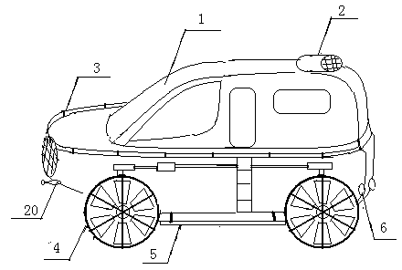
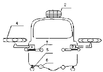
[0022] A land and spaceship of the present invention such as figure 1 , figure 2 , as shown, mainly consists of casing 1, tire 4, railing 3, engine, navigation system, transmission system, control system, automobile assembly, landing gear 5, water wheel drive 6, steering rudder 2, weapon attack system and cab constitute. The landing gear is positioned at the bottom of the casing, the steering rudder 2 is positioned above the rear of the casing, the water wheel driver is positioned at the bottom of the casing rear, and the railing is positioned around the casing. The tires are dual-purpose tires for mobile road walking and flying wheels, such as Figure 7 Shown, tire is made of rubber tire 8, wheel rim 9, adjusting blade 11 and support column 10, and adjusting blade is connected with central axle sleeve 14 through blade connecting hole 12, and support column inserts intermediate axle sleeve. The diameter o...

Embodiment 2

[0024] Embodiment 2 Airship with mechanical transmission structure

[0025] Another embodiment of the present invention is as Figure 5 , Image 6 As shown, it is a land spacecraft with a mechanical transmission structure. Including gearbox 47 , drive shaft 45 , differential 46 , folding shaft 42 , angle adjuster 36 and transfer case 13 , folding shaft 42 and angle adjuster 36 are driven by cone wheel 35 . The engine 32 is connected with the tire 4 through a gearbox 47 , a differential 46 , a transmission shaft 45 , a transfer case 44 and a folding shaft 42 . The engine is connected with the water wheel driver 6 through a transmission shaft 45 and a transfer case 44 . A B brake 43 is provided between the transfer case and the folding shaft. The transmission shaft 10 is connected to the tire 4 via the folding shaft 42 , the angle adjuster 36 and the rotor 21 . A shock-absorbing inner sleeve 40, an angle adjustment sleeve 39 and a fixed plate 38 are arranged between the fold...


PUM

PropertyMeasurementUnit
Diameteraaaaaaaaaa
Lengthaaaaaaaaaa

Abstract

The invention relates to a land airship which is composed of a machine casing, a steering rudder, guardrails, tires, a landing rack, a water wheel drive, an automobile assembly, an engine arranged in the machine casing, a navigation and control system and a weapon attack system. A rotor wing sternpost rudder is not needed, angle adjustment blades are arranged in the tires, blade angles can be closed, the land airship can drive on roads, and the land airship can vertical take off by increasing the blade angles to improve rotating speed. The land airship can be of a hydraulic structure or mechanical structure. The engine is connected onto the tires, the landing rack and the water wheel drive through a hydraulic transmission system or a mechanical transmission system. The control system adjusts automobile direction, tire folding, tire front flying inclination angles, tire inner blade angles and landing rack stretching and contracting through a servo motor control hydraulic system in sensing and numerical control mode. A continuous voyage emergency landing emergency hedge appliance is arranged in the land airship. The land airship has the advantages of being small in volume in taking off and simple in structure and capable of finishing vertical take-off and landing on roads and narrow spaces in courtyards, is three-purpose and can timely cope with various driving conditions in the sea, in the land and in the air.

Description

technical field [0001] The invention belongs to the technical field of transportation tools, and relates to a transportation tool for water, land and air, in particular to a spaceship on land. Background technique [0002] With the development of public transportation, the number of various means of transportation in cities and towns has doubled, and the resulting problem is that the development of roads cannot meet the needs of vehicles, and traffic jams and traffic accidents often occur. Can't get rid of it, affecting the completion of the task. For personnel in certain industries such as tourism, emergency rescue and surveying, it is not only necessary to travel on land, but sometimes it is necessary to fly in the air and travel in the water or sea to complete the task. Constantly changing the means of transportation on land, air and water not only wastes manpower and material resources, but also delays time. The civilian and military helicopters of the prior art are no...

Claims


Application Information

Patent Timeline
IPC IPC(8): B60F5/02
Inventor 冯计成冯关铭
Owner 冯计成
Learn More