
Pulse width modulation (PMW) modulator circuit

A modulating circuit and resistance technology, applied in the direction of electric lamp circuit arrangement, electric light source, lighting device, etc., can solve the problems of reduced dimming accuracy, different current, brightness deviation of LED light strings, etc., to achieve the effect of improving dimming accuracy

Inactive Publication Date: 2014-05-14
UNIV OF ELECTRONICS SCI & TECH OF CHINA
View PDF6 Cites 0 Cited by
  • Summary
  • Abstract
  • Description
  • Claims
  • Application Information

AI Technical Summary

Problems solved by technology

[0003] (1) In the application of multiple strings of LEDs, due to the difference in the characteristics of the LEDs, the current on each string of LEDs is different, resulting in a deviation in the brightness of the LED light strings in each dimming cycle
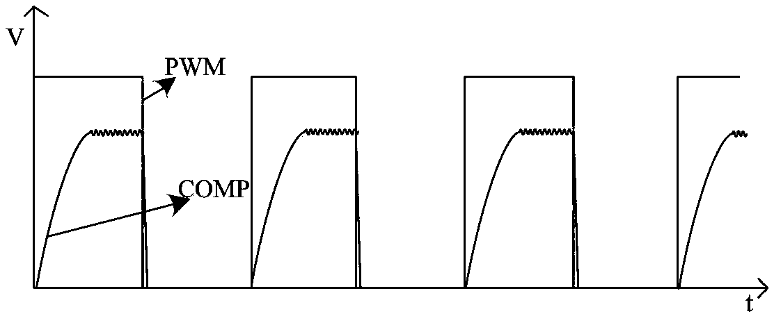
[0004] (2) Since the establishment of the system loop takes a certain amount of time (such as figure 1 As shown: where the output signal COMP of the error amplifier represents the establishment process of the system loop), then the loss of brightness will inevitably be introduced when the LED is turned on, resulting in a decrease in PWM dimming accuracy

Method used


Image

  • Pulse width modulation (PMW) modulator circuit
  • Pulse width modulation (PMW) modulator circuit
  • Pulse width modulation (PMW) modulator circuit

Examples


Embodiment Construction

[0017] Based on the two problems of traditional PWM dimming mentioned in the background technology, the following considerations are made:

[0018] 1. In multi-channel applications, the duty cycle of the PWM signal can be dynamically adjusted according to the actual value of the LED current of each channel to realize that the brightness of each LED in any dimming cycle is equal and is the preset value: I LED ×DT, where, I LED It is the average current on the LED when the PWM signal is at an effective high level in the dimming period, T is the period of the digital pulse PWM signal, and D is its duty cycle. In addition, it is assumed here that the LED current is turned off quickly, and the influence of the PWM signal off time on the brightness is ignored.

[0019] 2. According to the real-time brightness of the LED, it can accurately and dynamically adjust the duty cycle of the PWM signal that the internal circuit actually participates in dimming, reduce or even completely eli...


PUM


Abstract

The invention discloses a pulse width modulation (PMW) modulation circuit which specifically comprises a first transmission door, a first current comparer, a first alternative selector, a reset set (RS) trigger, two input nor gates, a phase inverter, a first N-channel metal oxide semiconductor (NMOS) tube, an error accumulation capacitor and a comparer with the selection function. The PMW modulator circuit can certainly modulate external input PWM signals according to current actually flowing through a light-emitting diode (LED), the duty ratio is adjusted, the duty ratio of the PWM signals actually participating in dimming in the circuit can be dynamically and correspondingly modulated as actual current change of the LED, and a signal driving switch of the LED is controlled to enable the luminance of the LED in all digital pulse periods to be equal to a preset value to improve PME dimming accuracy.

Description

technical field [0001] The invention belongs to the field of integrated circuits and specifically designs a PWM modulation circuit, which is used in LED backlight chips to improve the precision of PWM dimming. Background technique [0002] As an important dimming method of LED backlight chips, PWM dimming has the advantages of simple application and high efficiency. In addition, compared with analog dimming, PWM dimming has the advantages of high precision, good linearization, and no color shift. . But the traditional PWM dimming has the following problems: [0003] (1) In the application of multiple strings of LEDs, due to the differences in the characteristics of the LEDs, the current on each string of LEDs is different, resulting in a deviation in the brightness of the LED light strings in each dimming cycle. [0004] (2) Since the establishment of the system loop takes a certain amount of time (such as figure 1 As shown: where the output signal COMP of the error ampli...

Claims


Application Information

Patent Timeline
Patent Type & Authority Patents(China)
IPC IPC(8): H05B37/02
Inventor 周泽坤王鑫张竹贤吴传奎石跃明鑫张波
Owner UNIV OF ELECTRONICS SCI & TECH OF CHINA
Learn More