
Chaotic laser controller

A chaotic laser and laser technology, applied in lasers, laser parts, phonon exciters, etc., can solve the problems of complexity and small modulation range, and achieve the effects of convenient operation, not easy to electromagnetic interference, and simple structure

Inactive Publication Date: 2014-02-05
HARBIN ENG UNIV
View PDF7 Cites 0 Cited by
  • Summary
  • Abstract
  • Description
  • Claims
  • Application Information

AI Technical Summary

Problems solved by technology

However, the system is relatively complicated, and the filter modulation is performed after the chaotic laser is generated, and the modulation range is small.

Method used


Image

  • Chaotic laser controller
  • Chaotic laser controller
  • Chaotic laser controller

Examples


Embodiment approach 1

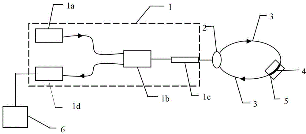
[0024] figure 1 It is a schematic diagram of using the temperature control device to adjust the temperature to control the chaotic laser output of the laser. The specific implementation method is as follows:

[0025] figure 1 The erbium-doped fiber laser selected in the above can be DFB or DBR. Here we take the DBR type as an example, and its structure diagram is as follows image 3 shown. The resonant cavity of the DBR is composed of two fiber gratings with the same Bragg wavelength welded at both ends of a section of erbium-doped optical fiber. The two gratings are used as cavity mirrors, and a certain length of high-doped Er 3+ The optical fiber is used to provide optical gain, and the pump light source is coupled into the resonator through a wavelength division multiplexer (WDM). 3+ The particle number inversion is formed in the optical fiber to generate stimulated radiation light, and the laser output with a wavelength of about 1548nm is obtained through the second f...

Embodiment approach 2

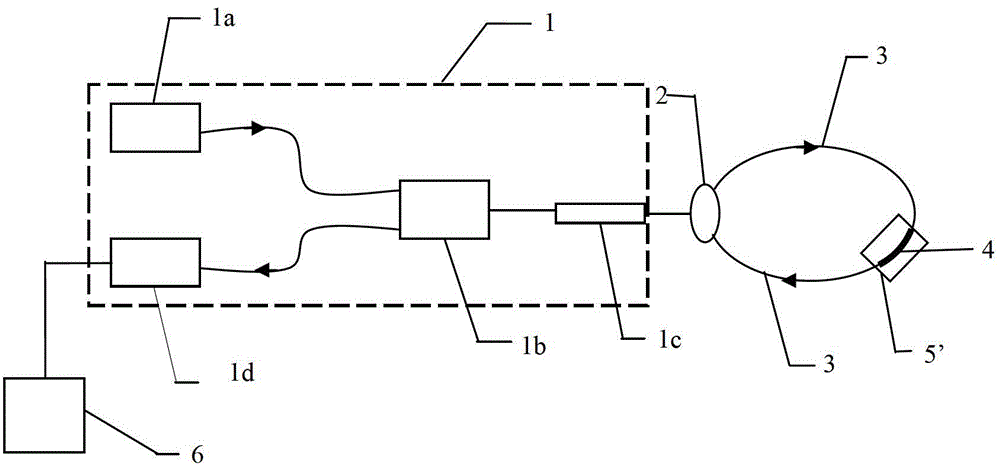
[0029] Such as figure 2 Shown is a structural schematic diagram of controlling the chaotic laser output of the laser by adjusting the stress acting on the multimode fiber. The specific implementation method is similar to Embodiment 1, the only difference is that in this solution, the stress applied to the multimode fiber is changed by adjusting the voltage and frequency applied to the PZT 5', and the stress of the multimode fiber is changed by controlling the magnitude of the stress. The wavelength and light intensity in the sag of the transmission spectrum can finally achieve the purpose of tuning the chaotic laser output.

[0030] The principle of the control of the chaotic laser output in the present invention is as follows: the light is output by a 980nm pump light source, and enters the DBR erbium-doped fiber laser after passing through the WDM. The Bragg fiber grating in the erbium-doped fiber laser constitutes the cavity mirror of the laser, and the light source is in ...


PUM


Abstract

The invention belongs to the control field of multimode fiber sensing chaotic lasers, and particularly relates to a control system for multimode fiber modulation chaotic laser. The chaotic laser controller comprises an Erbium-doped fiber laser, a circulator, a single-mode-multimode-single-mode fiber structure, an optical detector and an environmental control device, wherein laser generated in the Erbium-doped fiber laser enters the single-mode-multimode-single-mode fiber structure from one end of the circulator, is led out from the other end of the circulator and then enters a resonant cavity of the Erbium-doped fiber laser to become feedback light and generate chaotic laser; the chaotic laser enters the optical detector through a wavelength division multiplexer in the Erbium-doped fiber laser; and the environmental control device is mounted at a multimode fiber in the single-mode-multimode-single-mode fiber structure so as to control the environment outside the multimode fiber. The chaotic laser controller has the characteristics of capabilities of adjusting the wavelength, the intensity and the like of feedback light, convenience in operation, simple structure, low probability of electromagnetic interference, wide wavelength adjustment range and the like.

Description

technical field [0001] The invention belongs to the field of chaotic laser control for multimode optical fiber sensing, in particular to a control system for multimode optical fiber modulation chaotic laser. Background technique [0002] In 1975, H·Haken proved that the single-mode Maxwell-Bloch laser equation of the classical theory of uniform broadening radius is equivalent to the Lorenz equation in form, which opened up a new field of laser chaos research. According to the conditions of laser output stability, it can be divided into three categories: A, B, and C. Class A and Class B lasers have output instability under external disturbances, and Class C lasers may have output instability. It can be said that the instability of laser output is a common phenomenon, and the generation of chaotic laser is the result of laser instability. A special case of sex. As a special form of laser output, chaotic laser means that the output (light intensity, wavelength or phase) of th...

Claims


Application Information

Patent Timeline
Patent Type & Authority Patents(China)
IPC IPC(8): H01S3/10
Inventor 张建中刘亚南赵衍双李保勇孙伟民
Owner HARBIN ENG UNIV
Learn More