
Earthing switch for direct current valve hall

A technology of grounding switch and DC valve, which is applied in the direction of switches with movable electric contacts, can solve the problem of large span of torque output parts, and achieve the effect of saving range

Active Publication Date: 2012-12-19
HENAN PINGGAO ELECTRIC +2
View PDF2 Cites 7 Cited by
  • Summary
  • Abstract
  • Description
  • Claims
  • Application Information

AI Technical Summary

Problems solved by technology

[0004] The purpose of the present invention is to provide a grounding switch for a DC valve hall to solve the problem in the prior art that the torque output member and the transmission base have a large span in the axial direction of the grounding conductive rod

Method used


Image

  • Earthing switch for direct current valve hall
  • Earthing switch for direct current valve hall
  • Earthing switch for direct current valve hall

Examples


Embodiment Construction

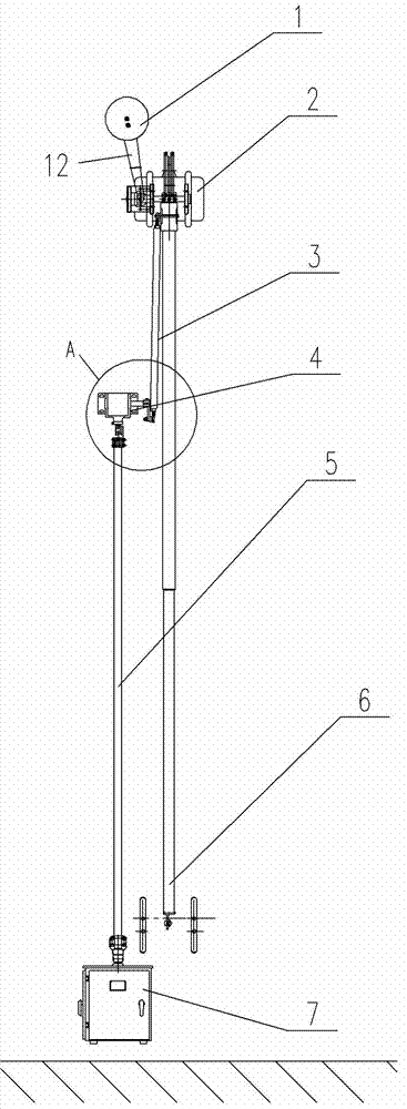
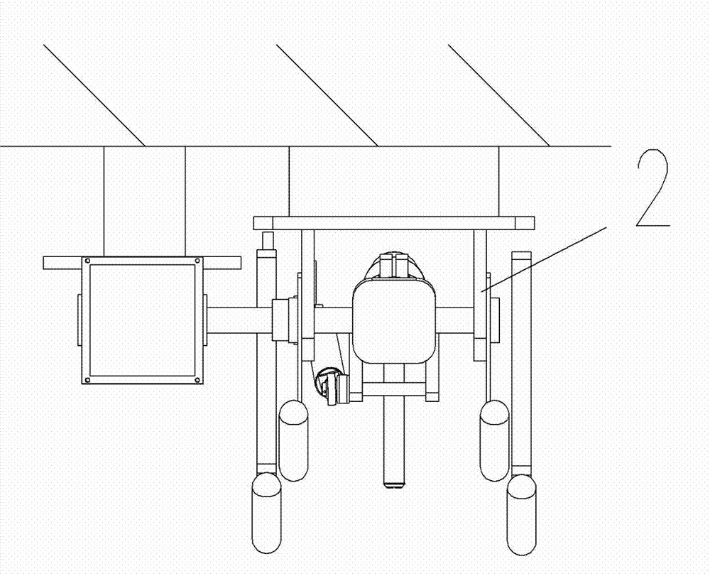
[0013] An embodiment of a grounding switch for a DC valve hall Figure 1~5 As shown: it includes a grounding conductive rod mechanism and a driving device. The grounding conductive rod mechanism includes a grounding conductive rod 6 and a transmission base 2 for installation on the wall 20 of the corresponding valve hall. One end of the grounding conductive rod 6 is used to install the corresponding dynamic The other end of the contact 13 is fixed with a rotating shaft of the conductive rod that is rotatably matched with the transmission base 2. The rotating axis of the rotating shaft of the conductive rod extends along the left and right directions. Through the rotating shaft of the conductive rod, the grounding conductive rod 6 can swing back and forth relative to the wall of the valve hall. The grounding conductive rod mechanism also includes a counterweight structure that is connected to the rotating shaft of the conductive rod through a balance transmission mechanism to ap...


PUM


Abstract

The invention relates to an earthing switch for a direct current valve hall. The earthing switch comprises an earthing conductive rod and a drive mechanism used for driving the earthing conductive rod to forwards and backwards swing relative to the wall surface of the valve ball, wherein the drive mechanism comprises an operating mechanism and a conductive rod transmission mechanism, the conducive rod transmission mechanism comprises a gearbox, the output end of the gearbox is provided with a second transmission shaft with a rotation axial line extending along the left-right direction, a first connecting rod is fixedly arranged on the second transmission shaft, the conductive rod transmission mechanism also comprises a third connecting rod fixedly connected with the earthing conductive rod, the conductive rod transmission mechanism also comprises a second connecting rod, two ends of the second connecting rod are respectively connected and hinged with the first connecting rod and the third connecting rod, the input end of the gearbox is provided with a first transmission shaft with a rotating axial line extending along an up-down direction, and the operating mechanism comprises a torque output member used for being arranged below the gearbox and being in transmission connection with the first transmission shaft. The invention solves the problem of large span of the torque output member and a transmission base in the axial direction of the earthing conductive rod in the prior art.

Description

technical field [0001] The invention relates to the field of DC power transmission and transformation equipment, in particular to a grounding switch for a DC valve hall. Background technique [0002] With the continuous and rapid development of my country's economy, power consumption has maintained a high-speed growth. In order to meet the future development of the national economy, the construction of ultra-high voltage and ultra-high voltage direct current transmission will be increased. DC transmission has the advantages of long transmission distance, good regulation performance, low overvoltage level, and small line loss. It is suitable for long-distance high-power transmission, interval grid interconnection peak regulation, and submarine cable transmission. [0003] As the key equipment of DC transmission, the safety of the equipment in the valve hall where the converter valve is installed is very important. The grounding switch in the valve hall is an important part of...

Claims


Application Information

Patent Timeline
IPC IPC(8): H01H31/28
Inventor 胡延涛赵维全尹天朔王占杰孙玉洲王巧红马永旭夏立国张任
Owner HENAN PINGGAO ELECTRIC
Learn More