
Novel LED total reflection lens capable of realizing continuous zooming and design method of novel LED total reflection lens

A total reflection and total reflection surface technology, applied in refractors, lighting and heating equipment, components of lighting devices, etc., can solve the problems of reduced beam uniformity, inability to collect large-angle beams, and large system volume, etc., to achieve Easy to install and adjust, improve the utilization rate of light energy, and the effect of small system volume

Inactive Publication Date: 2012-12-19
CHANGCHUN INST OF OPTICS FINE MECHANICS & PHYSICS CHINESE ACAD OF SCI
View PDF4 Cites 3 Cited by
  • Summary
  • Abstract
  • Description
  • Claims
  • Application Information

AI Technical Summary

Problems solved by technology

First, the structure cannot collect large-angle beams, resulting in a waste of light energy
Second, because the number of lenses is often more than one, the system volume is relatively large
Finally, the design freedom of the traditional lens structure is low, and the structure designed for one or two modes is only better in this mode, and the beam uniformity is significantly reduced after deviation

Method used


Image

  • Novel LED total reflection lens capable of realizing continuous zooming and design method of novel LED total reflection lens
  • Novel LED total reflection lens capable of realizing continuous zooming and design method of novel LED total reflection lens
  • Novel LED total reflection lens capable of realizing continuous zooming and design method of novel LED total reflection lens

Examples


Embodiment Construction

[0014] The present invention will be described in further detail below in conjunction with the accompanying drawings and embodiments.

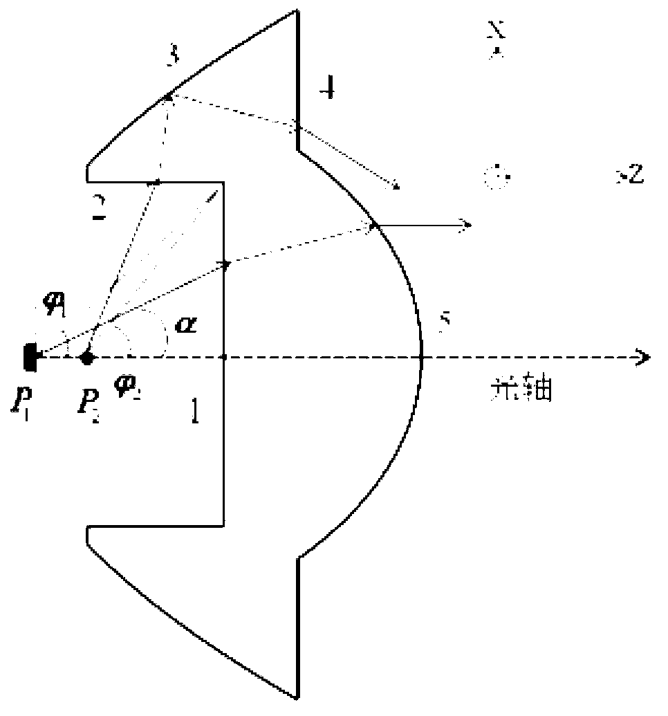
[0015] like figure 1 As shown, a new type of LED total reflection lens that realizes continuous zooming, the lens includes: a bottom cavity composed of plane 1 and plane 2, a total reflection surface 3, a peripheral plane 4 and a central transmission surface 5, the total reflection surface 3 Connected to the bottom cavity 1 and the peripheral plane 4, the peripheral plane 4 is connected to the central transmission surface 5, the bottom cavity, the total reflection surface 3, the peripheral plane 4 and the central transmission surface 5 are symmetrical to the optical axis, the total reflection surface 3 and The transmission surfaces 5 are all free-form surfaces. Light source at position P 1 When the beam is collimated through the central transmission surface, at P 2 When the beam diverges. When the LED is in position P 1 hour, The light ...


PUM


Abstract

The invention discloses a novel LED total reflection lens capable of realizing continuous zooming and a design method of the novel LED total reflection lens, and belongs to the field of semiconductor illumination. The lens comprises a bottom containing cavity, a total reflection surface, a peripheral plane and a central transmission surface, the total reflection surface and the bottom containing cavity are connected with the peripheral plane, the peripheral plane is connected with the central transmission surface, the bottom containing cavity, the total reflection surface, the peripheral plane and the central transmission surface are symmetric around an optical axis, and both the total reflection surface and the central transmission surface are free-form surfaces. The novel LED total reflection lens realizes continuous zooming by a single total reflection lens, and is convenient to mount and adjust, and a system is small in size and. By the design method, light energy is distributed in a free-form surface manner, so that light energy utilization rate of the system and illuminance uniformity degree of a target surface are increased.

Description

technical field [0001] The invention belongs to the field of semiconductor lighting and relates to a novel LED total reflection lens and a design method for realizing continuous zooming. Background technique [0002] Today, LEDs are widely used in various fields due to their long life, low energy consumption and many other advantages, such as road lighting, LED projectors and indoor lighting and so on. In many applications, the distance between the illuminated target surface and the light source and the field of view of the beam are not fixed. For example, the infrared lighting equipment used in the night monitoring system is required to be able to change its own angle according to the zoom range of the infrared camera. The field of view and energy density distribution make the irradiation range cover the entire monitoring area. If the field of view of the infrared lamp is too large, it will cause waste of light energy, otherwise it will produce a flashlight effect and affec...

Claims


Application Information

Patent Timeline
IPC IPC(8): F21V5/04F21Y101/02
Inventor 刘华辛迪卢振武
Owner CHANGCHUN INST OF OPTICS FINE MECHANICS & PHYSICS CHINESE ACAD OF SCI
Learn More