Descender with self- acting brake

A technology of protrusions and bases, which is applied to equipment for mountaineering, sports accessories, life-saving equipment, etc., and can solve problems such as ineffective functioning and jamming

Inactive Publication Date: 2012-12-12
CAPITAL SAFETY GROUP AUSTRALIA
View PDF8 Cites 9 Cited by
  • Summary
  • Abstract
  • Description
  • Claims
  • Application Information

AI Technical Summary

Problems solved by technology

However, one problem with this descender is that it does not function effectively and has a tendency to jam when used as an ascender to lift objects, bodies or the like

Method used


Image

  • Descender with self- acting brake
  • Descender with self- acting brake
  • Descender with self- acting brake

Examples


Embodiment Construction

[0050] Detailed Description of Preferred Embodiments

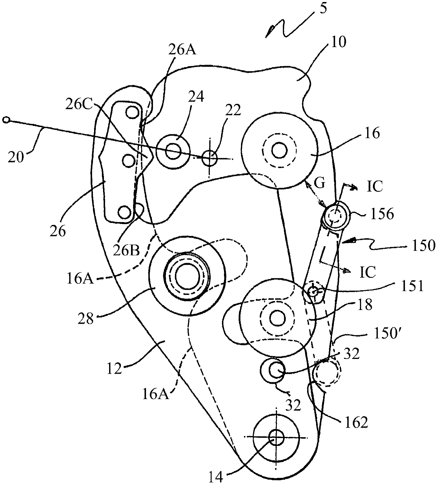
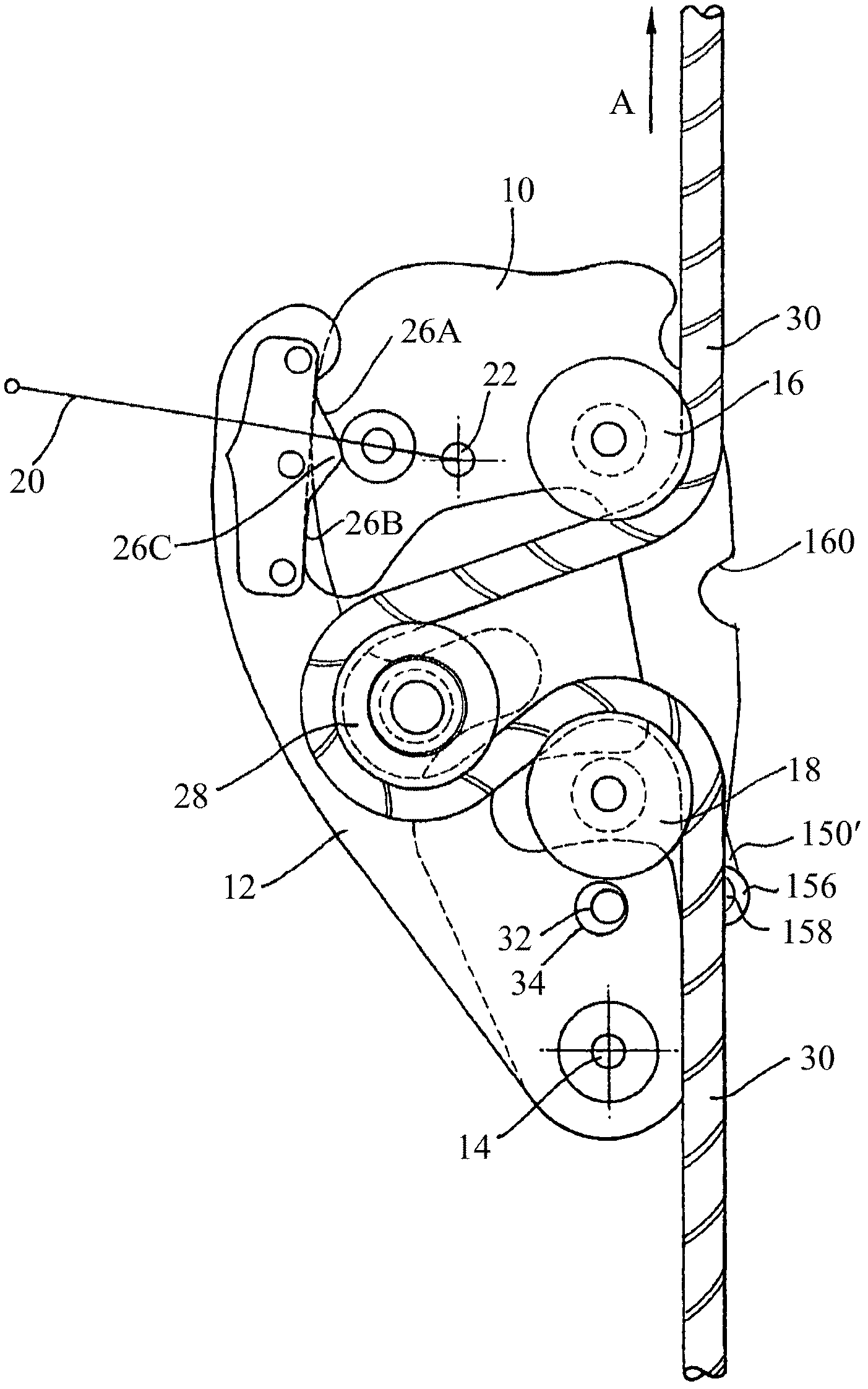
[0051] With reference to the accompanying drawings, figure 1 is a plan view of the descender, which includes a base plate 10 and an arm 12 . exist figure 1 In , the portion 16A of the outer edge of the base plate that is hidden from view by the arm is shown in dashed lines, as is the peripheral portion of the arm that is hidden from view by the pulley.

[0052] The arm 12 is mounted above the base plate 10 by means of a pivot 14 such that the arm is free to rotate about the pivot relative to the base plate. Spaced apart first pulleys 16 and second pulleys 18 are respectively mounted on the base plate. These pulleys are not rotatable. The pulley is configured such that part of the arm 12 can be inserted under the pulley and between the pulley and the base 10, as will be specifically referenced later. Figure 2A explained.

[0053] The lever 20 is also mounted to the base plate by means of a pivot 22 . exist figur...


PUM


Abstract

A descender (5) for use in abseiling or belaying, comprising a base (10) connected to a harness or the like, with first (16) and second (18) spaced projections engaging a rope, the projections (16, 18) both extending normal to the base (10); an arm (12) pivotally mounted to the base (10) at a pivot axis (14), the arm (12) having a third projection (28) for engaging a rope, the projection (28) extending parallel to the pivot axis (14) and being located so that when the arm (12) is pivoted towards the base (10), the third projection (28) is located between the first (16) and second (18) spaced projections, wherein a fourth projection (156) disposed generally between the first (16) and second (18) projections and adjacent an edge of the base (10) separates a portion of rope passing into the descender (5) and around the first (16) and third (18); projections from the portion of the same rope passing out of the descender (5) between the third (28) and second (18) projections.

Description

[0001] Cross References to Related Applications [0002] This application claims priority to Australian Provisional Patent Application No. 2009902729, entitled "Improved Descender", filed 12 June 2009, the entire content of which is hereby incorporated by reference. field of invention [0003] The present application relates to a descender for abseiling or belaying, and more particularly to an improved descender of the type including an automatic brake. Background of the invention [0004] Abseiling is a technique for descending a steep surface, such as a cliff wall, and is commonly used by people involved in activities such as mountaineering, canyoning, and caving. To descend down the cliff wall, one end of the rope is fastened to the top of the cliff, and the person descends, then slides down the rope. The rope is passed around the body, or more commonly through a descender attached to a harness worn by the person, so that the passage of the rope around the body or throug...

Claims


Application Information

Patent Timeline
Patent Type & Authority Applications(China)
IPC IPC(8): A62B1/14A62B1/18A63B29/02
CPCA62B1/14A62B1/18A63B29/00A63B29/02
Inventor 鲍里斯·罗格里亚
Owner CAPITAL SAFETY GROUP AUSTRALIA
Why Eureka
Try Eureka