Sputtering machine and control method for magnet thereof

A control method and technology of a sputtering machine, which are applied in the directions of sputtering coating, ion implantation coating, vacuum evaporation coating, etc., can solve problems such as increased production cost and edge detachment of target materials, so as to avoid waste and solve production problems. effect of cost increase

Inactive Publication Date: 2014-05-14
AU OPTRONICS CORP
View PDF6 Cites 0 Cited by
  • Summary
  • Abstract
  • Description
  • Claims
  • Application Information

AI Technical Summary

Problems solved by technology

[0005] The invention provides a control method of a sputtering machine and its magnet, wherein the magnet of the sputtering machine has two moving paths located on the same straight line, so as to solve the problem of too much noise on the edge of the target in the sputtering process of the prior art. Detachment, which in turn causes the problem of increased production costs
The target carrier is located in the chamber

Method used


Image

  • Sputtering machine and control method for magnet thereof
  • Sputtering machine and control method for magnet thereof
  • Sputtering machine and control method for magnet thereof

Examples


Embodiment Construction

[0073] According to an embodiment of the present invention, a sputtering machine is disclosed. The sputtering machine is suitable for carrying a substrate. The sputtering machine is used to perform a sputtering process on the substrate, so as to separate a target and form the target on the substrate.

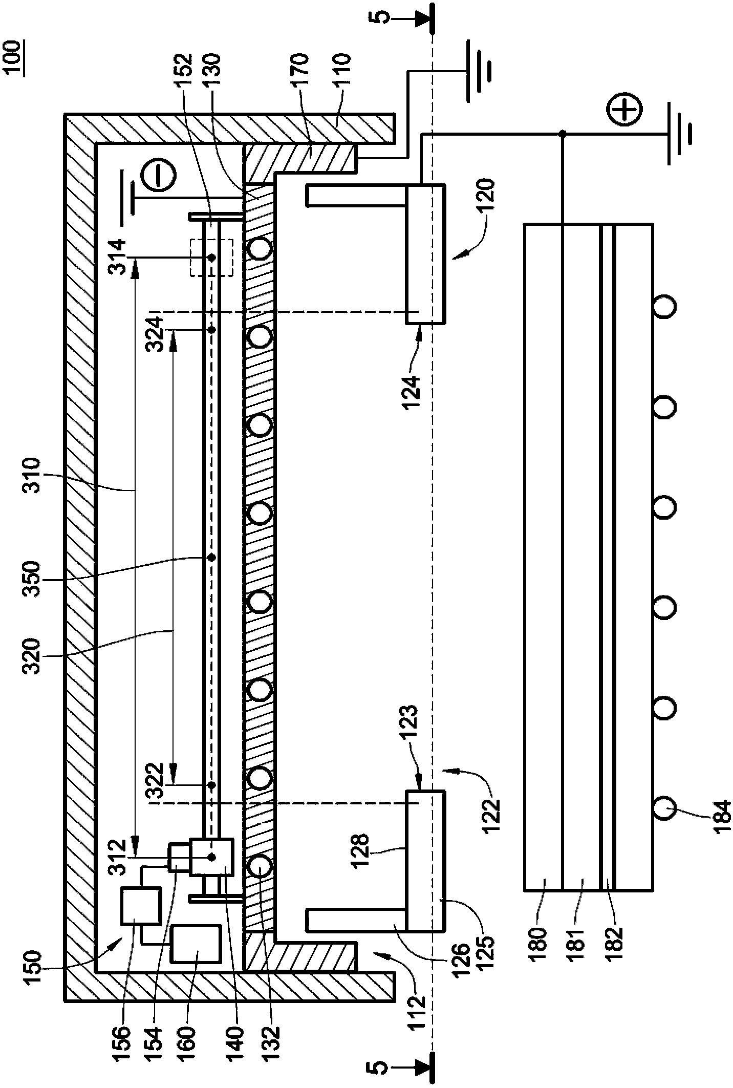
[0074] Please refer to figure 1 , figure 1 It is a schematic cross-sectional view of a sputtering machine according to an embodiment of the present invention. In this embodiment, the sputtering machine 100 includes a chamber 110 , a shield 120 , a target carrier 130 , a magnet 140 , a driving mechanism 150 and a programmable controller 160 .

[0075] The chamber 110 has a chamber opening 112 . The target carrier 130 is suitable for carrying a target (not shown). In addition, the target carrier 130 corresponds to the chamber opening 112 . For example, a cooling water channel 132 is provided in the target carrier 130 , and the cooling water channel 132 is used for cooling the ...


PUM


Abstract

A sputtering machine and a control method for a magnet thereof. The sputtering machine comprises a cavity chamber, a target material loading plate, a cover, a magnet, a drive mechanism and a programming controller. The cavity chamber has an opening. The target material loading plate is positioned in the cavity chamber. The cover covers the opening of the cavity chamber, and has a covering opening which is smaller than the cavity chamber opening and exposes the target material loading plate. The magnet is arranged in the cavity chamber. The drive mechanism is in connection with the magnet to drive the magnet to move on the target material loading plate. The programming controller is connected to the drive mechanism to drive the magnet to move along a first path with two first end points and a second path with two second end points, wherein both the first path and the second path span the covering opening, and the two second end points are between the two first end points. The space of magnet took up of the two first end points is not overlapped with that of the two second end points.

Description

technical field [0001] The invention relates to a metal thin film deposition device, in particular to a sputtering machine and a control method for a magnet thereof. Background technique [0002] In the process of liquid crystal display panels, plasma display panels, or semiconductor microcircuits, in order to make metal lines or metal contacts of various shapes, manufacturers need to form metal thin films on the substrates. Generally, methods for forming a metal thin film on a substrate can be classified into physical vapor deposition (Physical Vapor Deposition, referred to as PVD) method and chemical vapor deposition (Chemical Vapor Deposition, referred to as CVD) method. Among them, the PVD method can be mainly divided into a sputtering method, a resistance heating evaporation method, and an electron gun heating evaporation method. The so-called sputtering method refers to passing an inert gas (such as Argon, Argon for short) into a chamber of a sputtering machine in a v...

Claims


Application Information

Patent Timeline
Patent Type & Authority Patents(China)
IPC IPC(8): C23C14/34C23C14/54
Inventor 黄宇庆
Owner AU OPTRONICS CORP
Why Eureka
Try Eureka