Electrical connector and contact element thereof

A technology of electrical connectors and contacts, which is applied in the direction of connection, parts of connection devices, fixed/insulated contact components, etc., can solve the problems of increased production cycle, increased manufacturing cost, and complicated assembly process, so as to simplify the manufacturing process and structure, time saving, and manufacturing cost reduction effects

Inactive Publication Date: 2012-12-05
CHINA AVIATION OPTICAL-ELECTRICAL TECH CO LTD
View PDF7 Cites 2 Cited by
  • Summary
  • Abstract
  • Description
  • Claims
  • Application Information

AI Technical Summary

Problems solved by technology

As far as the press-fit method is concerned, it is mainly to open a step hole on the insulator, and set a shoulder protruding toward the radial periphery of the contact piece on the base of the contact piece. When assembling, one end of the shoulder of the base is covered by the step hole. The step surface on the wall of the hole is blocked, and the other end is fixed by an additional insulating plate. There are two fixing parts in this way, namely the insulator and the insulating plate. The assembly process is complicated, and both the insulator and the insulating plate need to be passed through a special Mold processing, which directly leads to the increase of the assembly process of the electrical connector, the increase of the production cycle and the increase of the manufacturing cost. In addition, in order to prevent the contact from rotating in the insulator, it is often necessary to set a special contact between the contact and the insulator. The anti-rotation structure, which also increases the complexity of the assembly process of the electrical connector to a certain extent
The injection molding packaging method is to directly inject the insulator on the contact piece through the corresponding mold. In order to prevent the contact piece from being bent during the packaging process, the diameter of the contact piece is generally required to be large and the material properties of the contact piece There are certain requirements. In addition, the contacts fixed in this way cannot be reused in different products. The above-mentioned series of reasons also lead to an increase in the cost of electrical connectors that use injection molding to fix the contacts.
[0003] To sum up, the current way of fixing the contacts and insulators of electrical connectors directly leads to an increase in the production cost of electrical connectors and a decline in market competitiveness.

Method used


Image

  • Electrical connector and contact element thereof
  • Electrical connector and contact element thereof
  • Electrical connector and contact element thereof

Examples


Embodiment Construction

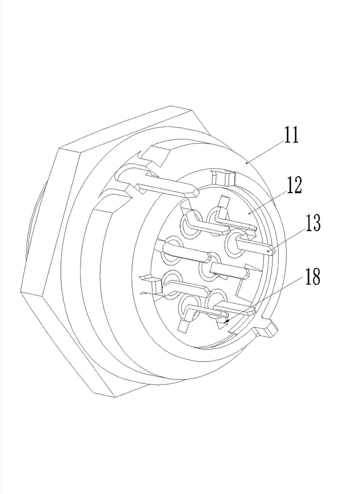
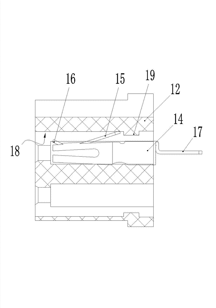
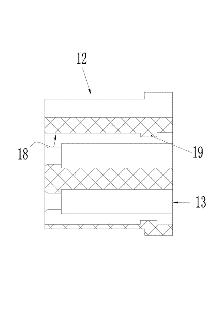
[0025] Embodiment 1 of the electrical connector of the present invention, such as Figure 1-4 As shown, a metal shell 11 is included, and an insulator 12 is fixedly installed in the shell 11. A mounting hole 13 is provided on the insulator 12, and a contact piece 14 is installed in the mounting hole 13. The contact piece 14 is a hole contact The component includes a base, the base is cylindrical and has an axis extending in the front-rear direction (plugging direction), the front part has a socket 14-1 for the insertion of the adapter pin, and the outer peripheral surface of the base is provided with elastic inversions. Thorn 15. In this embodiment, the elastic barb 15 is integrated with the base of the corresponding contact piece. The direction perpendicular to the front and back direction) extends outside and forms an overhanging structure, and a finger key 16 is also provided on the outer wall of the base of the contact piece 14. In this embodiment, the finger key 16 and th...


PUM


Abstract

The invention relates to the field of electrical connectors, in particular to an electrical connector and a contact element thereof. The electrical connector comprises an insulator and contact elements. The insulator is provided with mounting holes. Each contact element is provided with a base part which is spliced into the corresponding mounting hole from back to front. Each base part is provided with a forwards-backwards extended axis. An elastic barb is arranged on the base part of each contact element, and is gradually inclined and overhung towards the radial periphery of the base part from front to back. A forwards-backwards extended guide groove opposite to the elastic barb is formed on the hole wall of each mounting hole. Each elastic barb is matched with the corresponding guide groove to prevent the corresponding contact element from rotating in the corresponding mounting hole. A stopping table is arranged at the rear end of the groove bottom of each guide groove, and is matched with the rear end of the corresponding elastic barb to stop the corresponding contact element to backwards move relative to the insulator. A stepped surface facing a rear part is arranged on the front part of the hole wall of each mounting hole, and stops the front end of the corresponding base part to forwards move relative to the insulator. The production cost of the electrical connector is lowered.

Description

technical field [0001] The invention relates to the field of electrical connectors, in particular to an electrical connector and a contact piece thereof. Background technique [0002] The housing, the insulator and the electrical contact are the three major components of the electrical connector. In the current electrical connector, most of the contacts are fixed and assembled together through the base and the insulator. The fixing method of the base and the insulator is mainly There are two types, namely press-fit method and injection-molded packaging method. As far as the press-fit method is concerned, it is mainly to open a step hole on the insulator, and set a shoulder protruding toward the radial periphery of the contact piece on the base of the contact piece. When assembling, one end of the shoulder of the base is covered by the step hole. The step surface on the wall of the hole is blocked, and the other end is fixed by an additional insulating plate. There are two f...

Claims


Application Information

Patent Timeline
Patent Type & Authority Applications(China)
IPC IPC(8): H01R13/213H01R13/40H01R13/46
Inventor 武学顺胡国闯寇文博
Owner CHINA AVIATION OPTICAL-ELECTRICAL TECH CO LTD
Why Eureka
Try Eureka