
Device for attenuating creeping wave on antenna surface

A technology of creeping waves and antennas, which is applied in the field of devices for attenuating creeping waves on the surface of antennas, can solve problems affecting antenna performance, difficulty in identifying electromagnetic waves, and radar scanning accuracy. Effect

Active Publication Date: 2012-12-05
KUANG CHI INST OF ADVANCED TECH +1
View PDF3 Cites 3 Cited by
  • Summary
  • Abstract
  • Description
  • Claims
  • Application Information

AI Technical Summary

Problems solved by technology

[0003] In existing antennas, creeping waves will be generated on the surface of the antenna when electromagnetic waves are emitted, and the existence of creeping waves will affect the performance of the antenna. For example, in radar antennas, creeping waves will be generated at the same time when the radar antenna emits electromagnetic waves. In this way, it is difficult for us to identify whether the received electromagnetic wave is the radar wave reflected from the required reconnaissance object or the crawling wave, which has a great impact on the accuracy of radar scanning

Method used


Image

  • Device for attenuating creeping wave on antenna surface
  • Device for attenuating creeping wave on antenna surface
  • Device for attenuating creeping wave on antenna surface

Examples


Embodiment Construction

[0021] The present invention will be further described below in conjunction with the accompanying drawings and specific embodiments, but the embodiments of the present invention are not limited thereto.

[0022] A metamaterial is a new type of material with artificial microstructures as the basic unit, which is spatially arranged in a specific way and has a special electromagnetic response. It includes artificial microstructures and substrates for the attachment of artificial microstructures. The artificial microstructure is a planar structure or a three-dimensional structure composed of at least one metal wire that responds to electromagnetic waves. Multiple artificial microstructures are arranged in a periodic array on the substrate. Each artificial microstructure and the substrate it is attached to occupy A part is a metamaterial unit. The substrate can be any material different from the artificial microstructure. The superposition of these two materials produces an equival...


PUM


Abstract

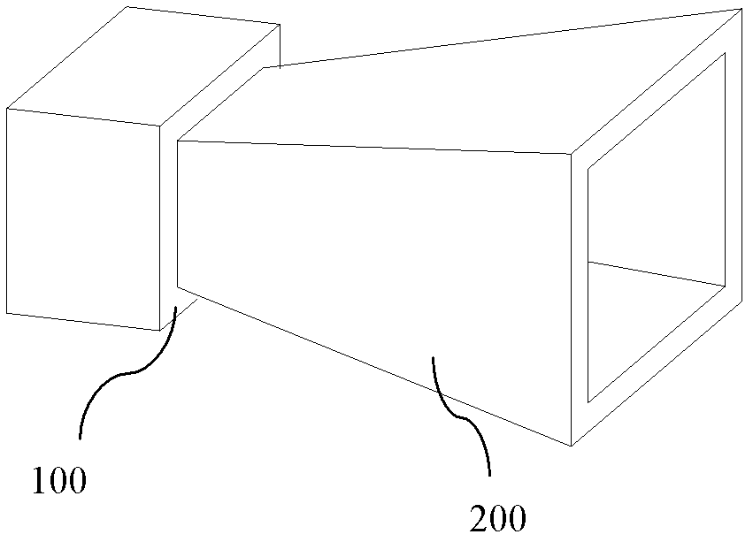
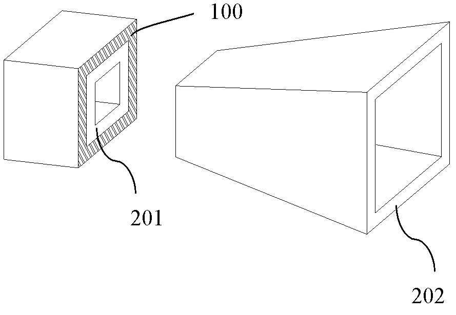
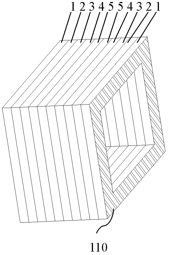
The invention relates to a device for attenuating creeping wave on antenna surface. The device comprises an antenna and a metamaterial film layer, wherein the antenna comprises a waveguide tube and a bell mouth; the metamaterial film layer consists of a plurality of metamaterial gradient layers, and is distributed on the surface of the waveguide tube of the antenna; and each metamaterial gradient layer comprises a platy substrate and a plurality of artificial microstructures arranged on the substrate. By the device, the metamaterial film layer is arranged on the surface of the antenna, and the creeping wave which occurs on the surface of the antenna is attenuated by changing refractive index of the metamaterial film layer, so that the influence of the creeping wave on the antenna can be greatly reduced to ensure that front-to-rear ratio of the antenna is obviously improved; and therefore, the high efficiency of the antenna is guaranteed.

Description

technical field [0001] The invention relates to the field of antennas, in particular to a device for attenuating antenna surface creeping waves. Background technique [0002] The diffraction phenomenon of electromagnetic waves is that the electromagnetic waves will go around when encountering obstacles or gaps smaller than the wavelength. However, part of the electromagnetic wave will continue to propagate along the smooth surface of obstacles or gaps. Such electromagnetic waves are called creeping waves. Creeping waves have two characteristics, that is, if the electromagnetic wave encounters protrusions, depressions, edges, discontinuities, gaps, gaps, and junctions of different materials during the propagation along the surface, the slope changes, that is, where the surface is discontinuous There will be a part of the electromagnetic wave returning by the original path. Another characteristic of creeping waves is that if the electromagnetic wave encounters the terminal o...

Claims


Application Information

Patent Timeline
IPC IPC(8): H01Q13/02H01Q19/00H01Q15/00
Inventor 刘若鹏季春霖岳玉涛宿超
Owner KUANG CHI INST OF ADVANCED TECH
Learn More