
Current sensing circuit, printed circuit board component and current sensor device

A printed circuit board, current sensing technology, applied in the direction of measuring current/voltage, measuring device, measuring device casing, etc., can solve the problem of inability to accurately measure transient current, reduce current measurement accuracy, weak output voltage signal, etc., to eliminate Effect of temperature drift, cancellation effect, accurate output voltage

Inactive Publication Date: 2012-12-05
SAE MAGNETICS (HK) LTD
View PDF17 Cites 13 Cited by
  • Summary
  • Abstract
  • Description
  • Claims
  • Application Information

AI Technical Summary

Problems solved by technology

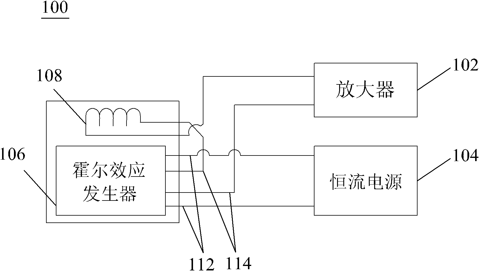
[0006] However, the above-mentioned current sensor 100 can only detect relatively large current due to the Hall effect, while the output voltage signal is weak and the accuracy is not high.
Distortion, temperature drift and other phenomena will occur in the circuit, thereby reducing the measurement accuracy of the current
Moreover, the sensitivity of the Hall element in the Hall effect generator 106 cannot accurately measure the continuously changing transient current

Method used


Image

  • Current sensing circuit, printed circuit board component and current sensor device
  • Current sensing circuit, printed circuit board component and current sensor device
  • Current sensing circuit, printed circuit board component and current sensor device

Examples


Embodiment Construction

[0042] Several different preferred embodiments of the present invention will now be described with reference to the accompanying drawings, wherein like reference numerals in different drawings represent like parts. As mentioned above, the essence of the present invention lies in a current sensing circuit with a negative feedback circuit, which can eliminate the temperature drift of the circuit under changing environment, so as to obtain an accurate voltage output.

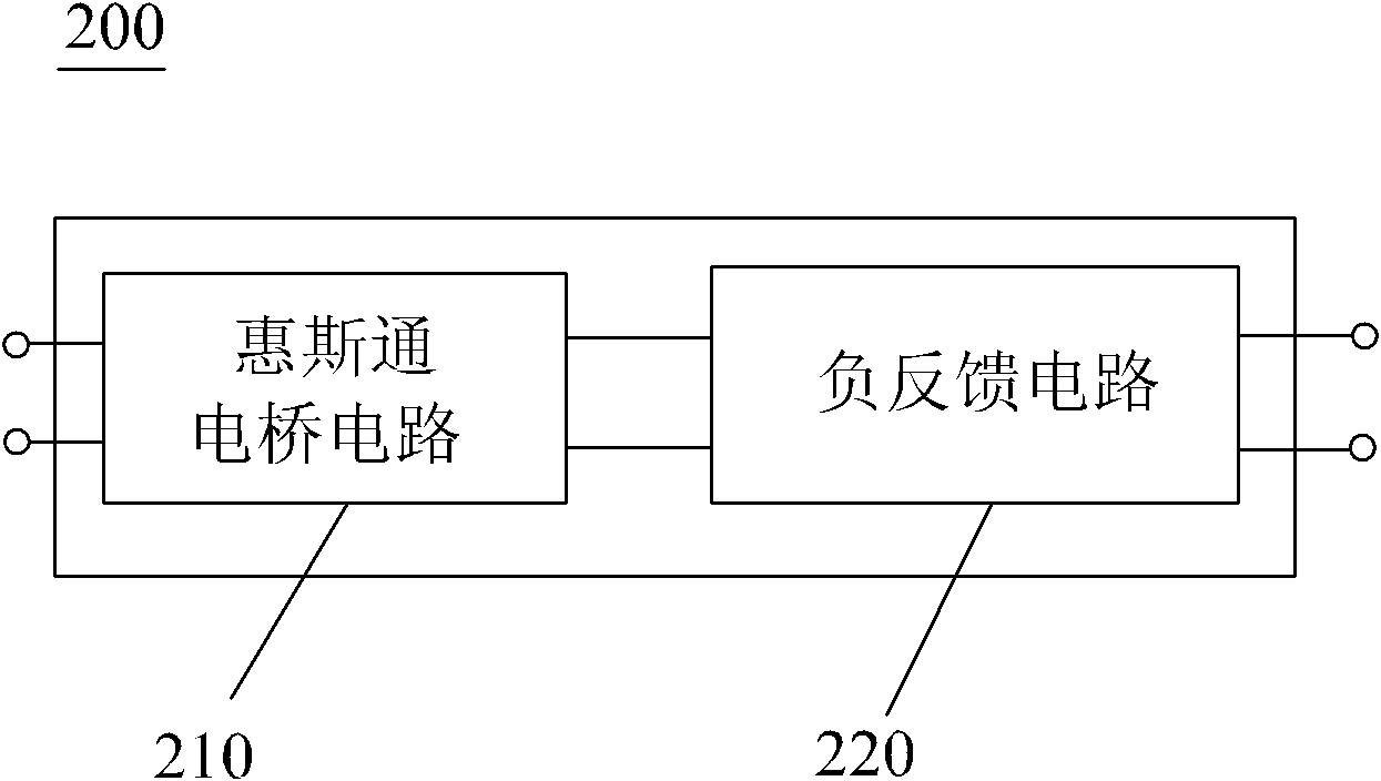
[0043] figure 2It is a structural block diagram of an embodiment of the current sensing circuit of the present invention. As shown in the figure, the current sensing circuit 200 includes a Wheatstone bridge circuit 210 and a negative feedback circuit 220 connected to the Wheatstone bridge circuit 210 . Specifically, the Wheatstone bridge circuit 210 is composed of four magnetoresistive elements, such as giant magnetoresistive (GMR) elements. Under the concept of the present invention, the magnetoresistive elemen...


PUM


Abstract

The invention discloses a current sensing circuit which comprises a Wheatstone bridge circuit and a negative feedback circuit. The Wheatstone bridge circuit is provided with at least four connected magnetoresistive elements and a pair of output ends. The magnetoresistive elements are used for sensing an external magnetic field with a first direction generated by a carrier electric conductor and outputting a differential signal. The negative feedback circuit is connected with the output ends, is driven by the differential signal and generates a magnetic field with a second direction opposite to the first direction, so that the influence of magnetoresistive element properties by temperature drift is eliminated. The temperature drift generated by the circuit under variable environments can be eliminated, and accurate voltage output is obtained.

Description

technical field [0001] The present invention relates to a current sensor device, and more particularly to a current sensing circuit with a negative feedback circuit for eliminating temperature drift of circuit components under changing environments. Background technique [0002] Currently, current sensors are widely used in the electronics industry. Generally, such a sensor includes a Hall effect (Hall effect) generator for sensing a magnetic field generated by a current, thereby generating a Hall effect output voltage proportional to the magnetic field. [0003] Hall-effect generators usually consist of the same semiconductor material as a Hall plate formed on an insulating substrate, as is common. An excitation current is applied to the Hall chip, and when the Hall effect generator is placed in a magnetic field and the excitation current is applied to it, the output voltage can be measured. [0004] Various sensing devices utilizing the Hall effect phenomenon have been u...

Claims


Application Information

Patent Timeline
Patent Type & Authority Applications(China)
IPC IPC(8): G01R19/32G01R1/04
CPCG01R15/205
Inventor 姚明高刘力兵山野井康友
Owner SAE MAGNETICS (HK) LTD
Learn More