Bearing seat sealing device for centrifugal fan

A centrifugal fan and sealing device technology, which is applied to the components of the pumping device for elastic fluid, mechanical equipment, machines/engines, etc., can solve problems such as poor sealing, achieve convenient assembly, small size, and prevent oil leakage Effect

Active Publication Date: 2012-12-05
JIN TONG LING TECH GRP CO LTD
View PDF8 Cites 6 Cited by
  • Summary
  • Abstract
  • Description
  • Claims
  • Application Information

AI Technical Summary

Problems solved by technology

[0006] Purpose of the invention: to overcome the defect of poor sealing of the traditional centrifugal blower bearing seat, and provide a combined centrifugal fan bearing seat sealing device that can realize two-way oil shifting

Method used


Image

  • Bearing seat sealing device for centrifugal fan
  • Bearing seat sealing device for centrifugal fan
  • Bearing seat sealing device for centrifugal fan

Examples


Embodiment 1

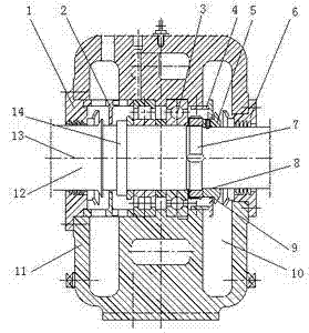
[0027] The retaining ring I2 is sleeved on the main shaft, one side is close to the outer ring of the bearing 3, and the other side is close to the sealing sleeve I1. The radial clearance between the retaining ring I2 and the main shaft is 0.3mm.

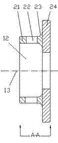
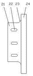
[0028] like figure 2 , image 3 As shown, the retaining ring II4 is welded by the vertical file 24 and the cross bar 21, and its axial section is a double T-shaped structure lying on its side. The screw hole on the crosspiece 21 is a long waist hole 22, which is convenient for adjusting the gap between the vertical rail 24 and the ring edge 9 when the retaining ring II4 is installed; Washers with different thicknesses are used to adjust the gap between the vertical rail 24 and the bearing seat 11 . The vertical rail 24 is perpendicular to the main shaft, and the cross rail 21 is parallel to the central axis 13 of the main shaft.

[0029] The oil slinger 5 is composed of a ring sleeve 8 and a ring edge 9 . The vertical file 24 o...

Embodiment 2

[0031] The retaining ring I2 is sleeved on the main shaft, and the other side of the retaining ring I2 is fastened to the bearing seat 11. The radial clearance between the retaining ring I2 and the main shaft is 0.4mm.

[0032] Retaining ring Ⅱ4 such as figure 2 , image 3 As shown, the crosspiece 21 of the retaining ring II4 is screwed together with the bearing seat 11, the vertical piece 24 is perpendicular to the main shaft, and the crosspiece 21 is parallel to the central axis 13 of the main shaft.

[0033] The radial gap between the vertical file 24 and the ring sleeve 8 is 0.4 mm; the axial gap between the vertical file 24 and the ring edge 9 is 0.8 mm.

[0034] The welding part of the vertical rail 24 and the cross rail 21 is a rounded corner 23 to reduce the stress generated during welding;

[0035] When the above embodiment 1 and embodiment 2 are working, the lubricating oil will splash out from the bearing 3 under the rotation of the high-speed main shaft and the...


PUM


Abstract

The invention provides a bearing seat sealing device for a centrifugal fan, in which a bearing is sleeved in the main shaft, a bearing seat is provided in the periphery of the bearing, a gland cover I is provided in one side of the bearing seat and a gland cover II is provided in the other side of the bearing seat. A check ring I is provided between the gland cover I and the bearing, and an oil retainer and a check ring II are provided between the gland cover II and the bearing. The axial profile of the check ring I is I-shaped, the axial profile of the check ring II is side-lying double-T-shaped, formed by soldering a horizontal bar and an erect bar, the erect bar being located in the periphery of the ring housing of the oil retainer, higher than the edge of the oil retainer. The bearing seat sealing device of the invention is compact in the structure, easy to process and convenient to assemble, and oil leakage of lubricating oil in the bearing seat can be prevented effectively during the site work, especially suitable for sealing a multistage centrifugal fan bearing seat.

Description

[0001] technical field [0002] The invention relates to a combined sealing device for a bearing seat of a centrifugal blower. Background technique [0003] Multi-stage centrifugal blowers are widely used in sewage treatment, metallurgy, electric power, and petrochemical fields. Due to the high speed of the blower, the lubricating oil splashes a lot under the rotation of the high-speed running bearing, and a special sealing structure is required to prevent the lubricating oil from between the main shaft and the shaft seal sleeve leak out. The conventional sealing structure is a labyrinth seal or a packing gland seal, which is not ideal for multi-stage centrifugal blowers with high speeds, and lubricating oil leakage is common in the use site. [0004] The patent specification with application number 201210045824.1 discloses "a fan bearing seat sealing device", including a main shaft, on which a bearing seat, a bearing, a bearing seat end cover and a gland are sequentially ...

Claims


Application Information

Patent Timeline
Patent Type & Authority Applications(China)
IPC IPC(8): F04D29/08F04D29/05
Inventor 秦树锋陆新明徐进赵红星
Owner JIN TONG LING TECH GRP CO LTD
Why Eureka
Try Eureka