A simple-supported and then continuous prefabricated monolithic composite continuous bridge and its construction method

A simply supported and then continuous, prefabricated girder technology, which is applied in bridges, bridge construction, erection/assembly of bridges, etc., can solve the problems of poor connection integrity of prefabricated bridges, slow manufacturing and installation speed, and high formwork amortization cost, etc., to achieve formwork The effect of low amortization cost, good beam synergy performance and convenient construction

Active Publication Date: 2016-10-05
杨众 +1
View PDF5 Cites 0 Cited by
  • Summary
  • Abstract
  • Description
  • Claims
  • Application Information

AI Technical Summary

Problems solved by technology

[0002] Traffic and municipal bridges with small and medium spans (12-30 meters) usually adopt prestressed box girder or girder bridges, and post-tensioning prestressed construction is mostly used. Or the slab is heavy, large-scale equipment is required for transportation and installation, and the manufacturing and installation speed is slow. The formwork of different specifications is used for the production of beams. It is necessary to grout in the steel strand casing. If the grouting is not dense, the prestressed steel bars will be corroded and the durability of the bridge will be poor, resulting in safety risks. The above-mentioned bridges use a large amount of steel and are expensive. I-shaped superimposed continuous bridge has not been reported yet

Method used


Image

  • A simple-supported and then continuous prefabricated monolithic composite continuous bridge and its construction method
  • A simple-supported and then continuous prefabricated monolithic composite continuous bridge and its construction method
  • A simple-supported and then continuous prefabricated monolithic composite continuous bridge and its construction method

Examples


Embodiment Construction

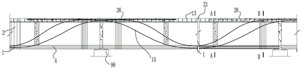
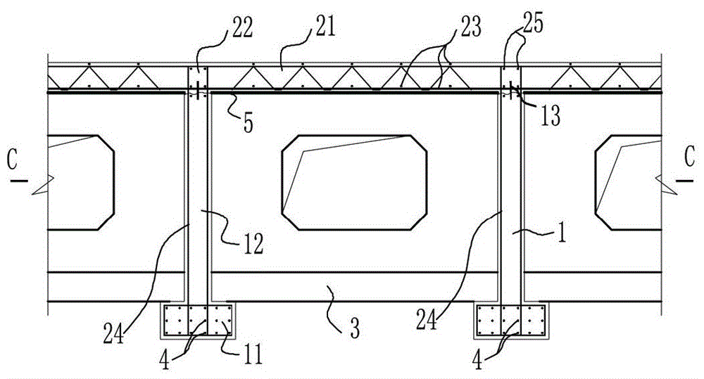
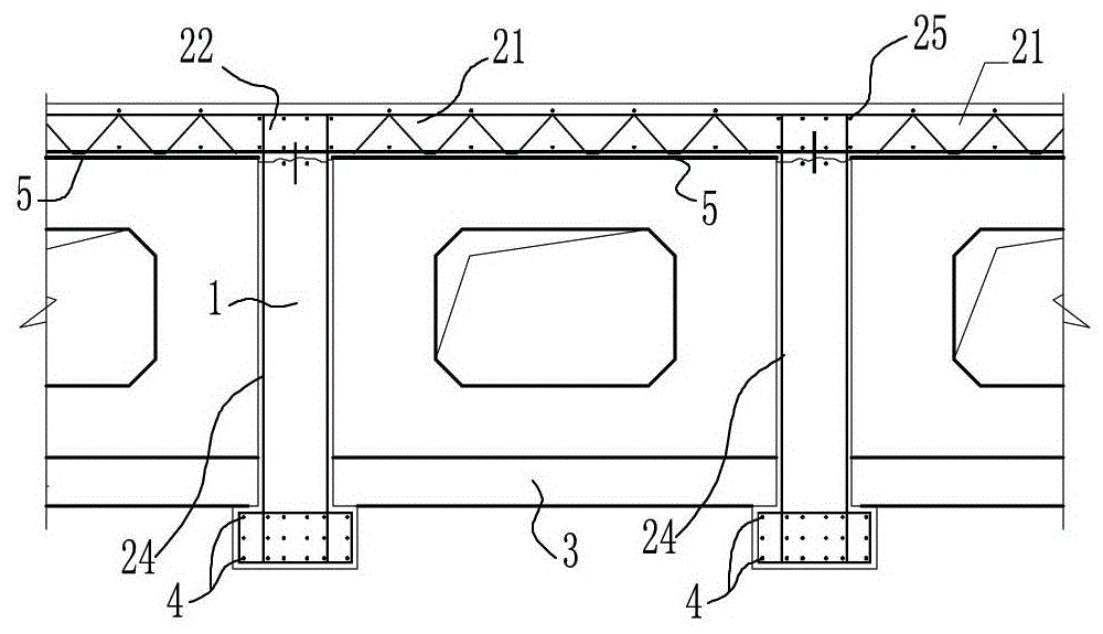
[0044] see Figure 1 to Figure 10 , an embodiment of a simple-supported and then continuous prefabricated monolithic laminated continuous bridge provided in the present invention includes an inverted T-shaped prestressed prefabricated beam part 1, a cast-in-place part 2 and a diaphragm 3. The pouring part 2 includes a cast-in-place slab 21 and a cast-in-place superimposed part 22 on the upper part of the beam. The lower flange 11 of the inverted T-shaped prestressed prefabricated beam 1 and the upper part of the web 12 are embedded with pre-tensioned prestressed steel strands 4. The transverse diaphragm 3 is a prefabricated plate, and the transverse diaphragm 3 is arranged between the webs 12 of adjacent inverted T-shaped prestressed prefabricated beams at a certain distance along the longitudinal direction, and is located above the lower flange 11 of the prefabricated beam 1 . In the present invention, a superimposed continuous bridge is formed by the prefabricated beam 1, t...


PUM


Abstract

A simply-supported-to-continuous prefabricated integrally-cast superposed continuous bridge comprises inverted-T-shaped pre-stress prefabricated beams, a cast-in-place portion and a transverse partition plate, and is characterized in that the cast-in-place portion comprises a cast-in-place plate and cast-in-place superposition portions on the upper portions of the beams, pre-tensioning pre-stressed steel wires are embedded into the bottom flange and the upper portion of a web of each inverted-T-shaped pre-stress prefabricated beam, a galvanized steel plate is arranged on the cast-in-place plate bottom surface between the two prefabricated beams, and the transverse partition plate is a prefabricated plate and perpendicularly arranged between the webs of the adjacent inverted-T-shaped beams above the flanges of the inverted-T-shaped beams at a certain distance. The inverted-T-shaped prefabricated beams are light in dead weight so as to be convenient to transport and mount and high in construction speed.

Description

technical field [0001] The invention relates to the field of bridge construction, in particular to a prefabricated integral bridge Background technique [0002] Traffic and municipal bridges with small and medium spans (12-30 meters) usually adopt prestressed box girder or girder bridges, and post-tensioning prestressed construction is mostly used. Or the slab is heavy, large-scale equipment is required for transportation and installation, and the manufacturing and installation speed is slow. The formwork of different specifications is used for the production of beams. It is necessary to grout in the steel strand casing. If the grouting is not dense, the prestressed steel bars will be corroded and the durability of the bridge will be poor, resulting in safety risks. The above-mentioned bridges use a large amount of steel and are expensive. The I-shaped superimposed continuous bridge has not been reported yet. Contents of the invention [0003] The technical problem to be...

Claims


Application Information

Patent Timeline
Patent Type & Authority Patents(China)
IPC IPC(8): E01D1/00E01D21/00
Inventor 杨峰
Owner 杨众
Why Eureka
Try Eureka