
Device for clamping workpiece of machine tool

A workpiece clamping and machine tool technology, which is applied in positioning devices, metal processing machinery parts, clamping, etc., can solve problems that affect processing accuracy, cannot guarantee workpiece shape and position tolerance, and affect workpiece processing quality, so as to ensure processing accuracy, The effect of improving the qualified rate of products

Inactive Publication Date: 2012-12-05
SUZHOU DONGLI MACHINERY
View PDF0 Cites 12 Cited by
  • Summary
  • Abstract
  • Description
  • Claims
  • Application Information

AI Technical Summary

Problems solved by technology

[0002] CNC machine tools have the characteristics of high efficiency, good flexibility, and stable and reliable processing quality. At present, most shaft parts are mainly processed by CNC machine tools. , to realize the clamping of the workpiece; using this clamping method, when the positioning reference plane installed in the three-jaw chuck is uneven and jumps, the length of the workpiece is unstable, and the accuracy of the positioning reference directly affects the subsequent The machining accuracy of the process; and when using the three-jaw chuck for clamping, the workpiece center at the end of the three-jaw chuck and the center of the workpiece at the rear top part cannot be completely and accurately guaranteed to be on the same level, resulting in the inability to guarantee the shape and position tolerance of the workpiece and affecting the processing quality of the workpiece

Method used


Image

  • Device for clamping workpiece of machine tool

Examples


Embodiment Construction

[0010] The present invention is described below in conjunction with accompanying drawing.

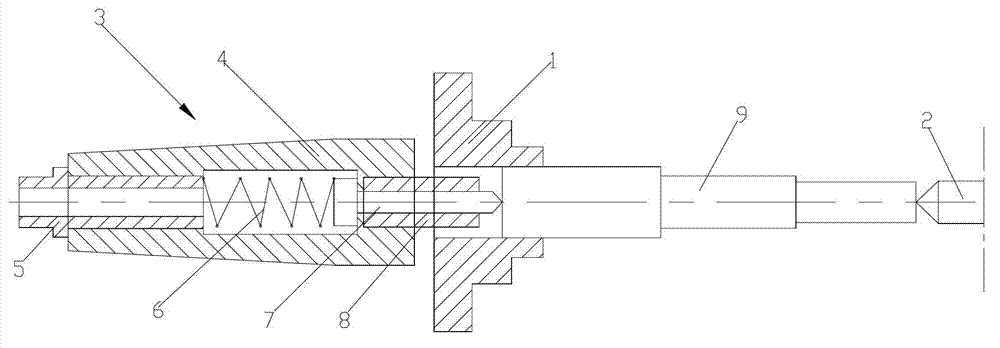
[0011] attached figure 1 It is a clamping device for a machine tool workpiece according to the present invention, which includes a three-jaw chuck 1 and a rear top 2, and an elastic movable top 3 is arranged behind the three-jaw chuck 1; the elastic movable top 3 includes a taper sleeve 4 ; The taper sleeve 4 is provided with a plug 5, a compression spring 6, and a front tip 7; the compression spring 6 is connected between the plug 5 and the front tip 7; the front tip 7 extends into the three-jaw chuck 1; The bar of the front center 7 is sleeved with a limit block 8 extending into the three-jaw chuck 1 ; the center of the front center 7 is on the same level as the center of the rear center 2 . Cooperate the center hole of the positioning reference end of the workpiece 9 with the front top 7, the front top 7 plays a centering role, and the other end of the workpiece 9 is supported by th...


PUM


Abstract

The invention discloses a device for clamping a workpiece of a machine tool. The device comprises a three-jaw chuck and a back tip, wherein an elastic movable tip is arranged behind the three-jaw chuck, and comprises a taper sleeve; a plug, a compression spring and a front tip are arranged in the taper sleeve; the compression spring is connected between the plug and the front tip; the front tip is extended towards the inside of the three-jaw chuck; a limit block which is extended towards the inside of the three-jaw chuck is sleeve on the rod part of the front tip; and the center of the front tip and the center of the back tip are positioned on the same horizontal line. Due to the adoption of the elasticity of the compression spring, the front tip can be stretched and retracted in the axial direction, is matched with a central hole at the positioning reference end of the workpiece all the time and has a centering effect, and the other end of the workpiece is pressed by the back tip, so that the front tip is compressed to the positioning reference end surface of the workpiece and then is contacted with the limit block, the three-jaw chuck is tightly locked, and the axis of the workpiece in the length direction and the center of the workpiece are positioned on the same horizontal line; and therefore, the machining accuracy of the workpiece is ensured, and the yield of a product is improved.

Description

technical field [0001] The invention relates to machining tools, in particular to a clamping device for machine tool workpieces. Background technique [0002] CNC machine tools have the characteristics of high efficiency, good flexibility, and stable and reliable processing quality. At present, most shaft parts are mainly processed by CNC machine tools. , to realize the clamping of the workpiece; using this clamping method, when the positioning reference plane installed in the three-jaw chuck is uneven and jumps, the length of the workpiece is unstable, and the accuracy of the positioning reference directly affects the subsequent The machining accuracy of the process; and when using the three-jaw chuck for clamping, the workpiece center at the end of the three-jaw chuck and the center of the workpiece at the rear top part cannot be completely and accurately guaranteed to be on the same level, resulting in the inability to guarantee the shape and position tolerance of the wor...

Claims


Application Information

Patent Timeline
IPC IPC(8): B23Q3/00B23B23/04
Inventor 叶晓峰
Owner SUZHOU DONGLI MACHINERY
Learn More