
Cutting and blanking mould for bar stock

A material mold and bar technology, which is used in the field of blanking molds for cutting round bars

Active Publication Date: 2012-12-05
隆昌山川机械有限责任公司
View PDF6 Cites 8 Cited by
  • Summary
  • Abstract
  • Description
  • Claims
  • Application Information

AI Technical Summary

Problems solved by technology

[0002]In the field of mechanical processing, a large number of round bars need to be cut and blanked. Common blanking methods include mold blanking or band saw blanking, etc., with The efficiency of the sawing method is low. Ordinary mold blanking uses a punch with a semicircular edge. After the bar is cut, it is unloaded by its own weight, which has the advantage of convenient unloading. One side of the surface is a free deformation zone. In the cutting zone, a huge collapse angle will be generated, and the end surface will be irregular, which will bring inconvenience to subsequent processing, cause additional material loss, bring huge economic losses to the enterprise, and also have problems such as low efficiency. ; If a punch with a full-circle cutting edge is used, there is a problem of difficult unloading

Method used


Image

  • Cutting and blanking mould for bar stock
  • Cutting and blanking mould for bar stock
  • Cutting and blanking mould for bar stock

Examples


Embodiment Construction

[0017] Below in conjunction with the accompanying drawings, the present invention will be further described in detail by taking the round bar as an example.

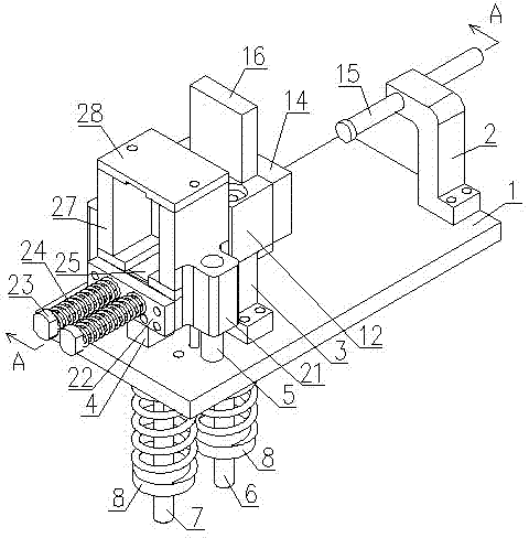
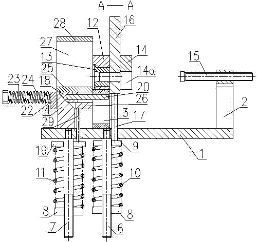
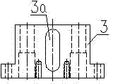
[0018] Depend on Figure 1 to Figure 7 As shown, the bar material cutting mold includes a base plate 1, a positioning seat 2 fixed on the base plate 1 by screws, a support 3, a wedge 4 and two guide posts 5, and two guide posts 5 fixed on the base plate 1 by threads. Pull rods 6 and 7 are fixed with a spring seat 8 on the two pull rods 6 and 7, a push plate 9 is slidably arranged on the pull rod 6 above the spring seat 8, and a spring is arranged between the spring seat 8 and the push plate 9 of the pull bar 6 10. A push plate 19 is slid on the pull rod 7 above the spring seat 8, and a spring 11 is provided between the spring seat 8 of the pull rod 7 and the push plate 19; the support 3 is provided with a long groove 3a, and the support 3 The upper end of the die is fixed with a die base 12 by bolts, the die 13 with an ...


PUM


Abstract

The invention discloses a cutting and blanking mould for a bar stock, which comprises a base plate, a positioning base, a supporting base, two pull rods, an inclined wedge and two guide pillars, wherein spring bases, push plates and springs are fixed on the two pull rods; a concave mould with an inner hole is fixedly arranged at the upper end of the supporting base; a convex mould cover plate is fixed on one side of the concave mould; a convex mould with the inner hole is slidably arranged between the convex mould cover plate and the concave mould; the convex mould is connected with one of the push plates; a material groove is arranged on the lower part of the convex mould cover plate; a slide block is arranged on an inclined surface of the inclined wedge; a pushing rod, a slide rail cover plate, a slide rail base plate, a rear baffle and a pushing pull rod are arranged around the slide block; the front end of the pushing rod is located in a long slot of the supporting base; a slide base is arranged on the two guide pillars; a withdrawing slot is arranged in the middle of the slide base; the inclined wedge is located in the withdrawing slot; a pushing spring is sleeved on the pushing pull rod; an upper linking plate is connected with the slide rail cover plate; and the slide rail base plate is connected with the other push plate. By using the cutting and blanking mould for the bar stock, the corner collapse phenomenon is greatly reduced, the material loss is reduced, the unloading is conveniently performed and the processing efficiency is high.

Description

technical field [0001] The invention relates to a blanking die, in particular to a blanking die for cutting round bars. Background technique [0002] In the field of mechanical processing, it is necessary to cut and blank round bars in large quantities. The common blanking methods include mold blanking or band saw blanking, etc. The efficiency of band saw blanking is low, and ordinary mold blanking uses For the punch with a semicircular cutting edge, the bar is unloaded by its own weight after being cut. Collapsing corners and irregular end faces will bring inconvenience to subsequent processing and cause additional material loss, which will bring huge economic losses to the enterprise and also have problems such as low efficiency. The problem. Contents of the invention [0003] The object of the present invention is to aim at the above-mentioned deficiencies of the prior art, to provide a bar material cutting die, which can greatly reduce the slump phenomenon, bring c...

Claims


Application Information

Patent Timeline
Patent Type & Authority Applications(China)
IPC IPC(8): B21D28/14
Inventor 颜川李斌
Owner 隆昌山川机械有限责任公司
Learn More