
Extruding mould

A technology of extrusion die and shunt bridge, applied in metal extrusion dies and other directions, can solve the problems of high production cost, cracking of shunt bridge, and short service life, so as to improve the life of the die, reduce the resistance of metal deformation, and improve the fluidity of metal. Effect

Active Publication Date: 2012-12-05
GUANGDONG HAOMEI ALUMINUM
View PDF5 Cites 6 Cited by
  • Summary
  • Abstract
  • Description
  • Claims
  • Application Information

AI Technical Summary

Problems solved by technology

[0002] In the process of metal extrusion, when the extruded metal encounters the straight shunt bridge and the core feed surface (crossing position of the shunt bridge), a metal flow dead zone is often formed, especially in the production process of thin-walled large-section hollow profiles. , such as large square pipes, round pipes and heterosexual pipes, the larger the core head, the greater the hydrostatic pressure and friction that the mold will bear, which will easily cause mold instability, excessive deformation, and even splitter bridge cracking, and a longer service life. Short, relatively high production cost

Method used


Image

  • Extruding mould
  • Extruding mould
  • Extruding mould

Examples


Embodiment Construction

[0015] In order to facilitate the understanding of those skilled in the art, the present invention will be further described in detail below in conjunction with the accompanying drawings and specific embodiments. It should be pointed out that the specific embodiments described here are only used to explain the present invention, not to limit the present invention.

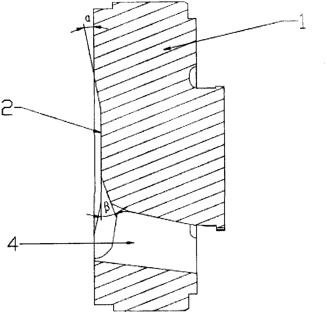
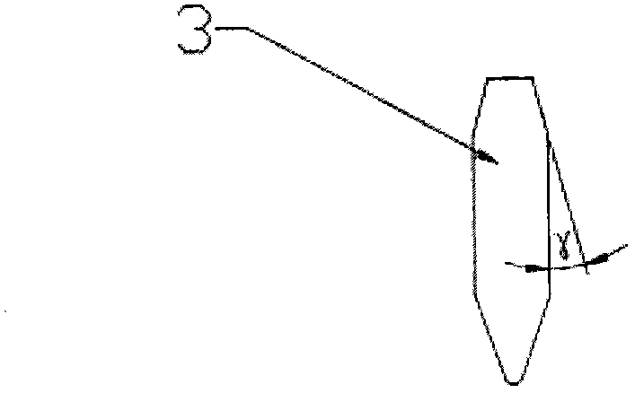
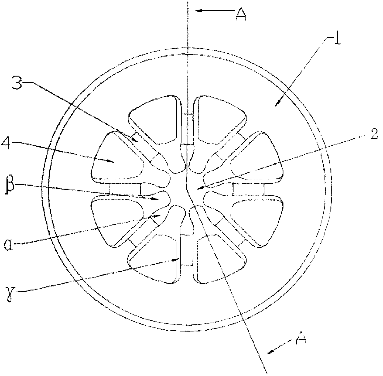
[0016] as attached figure 1 As shown, an extrusion die includes an upper die 1 and a lower die. The distribution bridges 3 in the shape of rice are distributed on the feed surface of the upper die. Uniform split holes 4 are formed between the split bridges, and the split bridges 3 intersect The concave surface 2 is formed below the feeding surface around it, and the diversion bridge 3 on the feeding surface and the concave surface 2 are transitioned at an oblique angle to form the first decompression angle α. The decompression angle β, the third decompression angle γ is provided on both sides of the shunt bridge 3...


PUM


Abstract

The invention relates to an extruding mould which comprises an upper mould and a lower mould, wherein flow-splitting bridges having a shape of Chinese character 'Mi' are distributed on a feeding surface of the upper mould; uniform flow-splitting holes are formed between the flow-splitting bridges; a crossing part of the flow-splitting bridges is lower than the peripheral feeding surface, thereby forming a concave surface; the flow-splitting bridges on the feeding surface and the concave surface are transited through an inclined angle, thereby forming a first pressure-reducing angle; a second pressure-reducing angle is arranged at a feeding port of the flow-splitting hole on the concave surface; and third pressure-reducing angles are arranged on the two sides of the flow-splitting bridges. According to the extruding mould, the flow-splitting bridges are reasonably arranged and the flow-splitting bridges and the feeding surface are designed in an optimized form, so that the remaining flowing dead area is reduced, the load-carrying capacity of the mould is improved and the service life of the mould is prolonged.

Description

technical field [0001] The invention relates to an extrusion die. Background technique [0002] In the process of metal extrusion, when the extruded metal encounters a straight shunt bridge and the core feed surface (crossing position of the shunt bridge), a metal flow dead zone is often formed, especially in the production process of thin-walled and large-section hollow profiles. , such as large square pipes, round pipes and heterosexual pipes, the larger the core head, the greater the hydrostatic pressure and friction the mold will bear, which will easily cause mold instability, excessive deformation, and even splitter bridge cracking, and a longer service life. Short, the production cost is relatively high. Contents of the invention [0003] In order to overcome the deficiencies and existing problems of the prior art, the present invention provides an extrusion die which can effectively improve the fluidity of metal and reduce the dead zone of metal flow. [0004] The...

Claims


Application Information

Patent Timeline
Patent Type & Authority Applications(China)
IPC IPC(8): B21C25/02
Inventor 董卫峰
Owner GUANGDONG HAOMEI ALUMINUM
Learn More