Lighting device, display apparatus, and television receiving equipment

A technology for a lighting device and a display device is applied in the fields of lighting devices, display devices and television receiving devices, which can solve the problems of increased cost of backlight source devices, inability to increase brightness, and increase in the number of light sources, and achieve excellent visual recognition and restraint consumption. Electricity, good display effect

Inactive Publication Date: 2012-11-28
SHARP KK
View PDF7 Cites 4 Cited by
  • Summary
  • Abstract
  • Description
  • Claims
  • Application Information

AI Technical Summary

Problems solved by technology

However, if the number of light sources is increased, the cost of the backlight unit increases, and power consumption also increases.
In addition, when the diffusion degree of the diffusion plate is increased, the brightness cannot be increased, and there is a problem that the number of light sources needs to be increased.

Method used


Image

  • Lighting device, display apparatus, and television receiving equipment
  • Lighting device, display apparatus, and television receiving equipment
  • Lighting device, display apparatus, and television receiving equipment

Examples


Embodiment approach 1

[0064] use Figure 1 to Figure 6 Embodiment 1 of the present invention will be described.

[0065] First, the configuration of a television receiver TV including a liquid crystal display device 10 will be described.

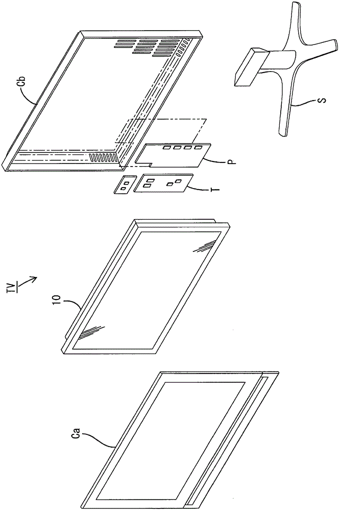
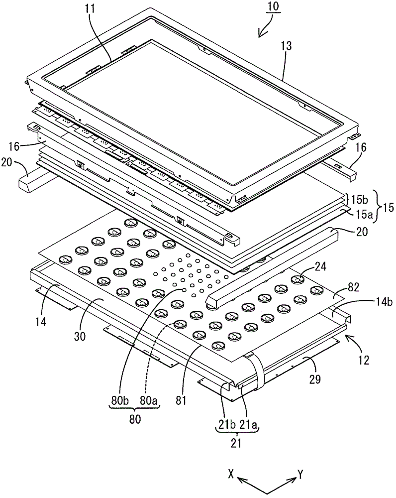
[0066] like figure 1 As shown, the television receiver TV of the present embodiment is configured to include: a liquid crystal display device 10; two front and back cabinets Ca, Cb housed in a manner sandwiching the liquid crystal display device 10; a power supply P; a tuner T; . The liquid crystal display device (display device) 10 has a horizontally long square shape as a whole, and is housed in a vertical state. like figure 2 As shown, this liquid crystal display device 10 includes a liquid crystal panel 11 as a display panel and a backlight device (illumination device) 12 as an external light source, and these are integrally held by a frame-shaped outer frame 13 or the like.

[0067] Next, the liquid crystal panel 11 and the backlight unit 12 constitut...

Embodiment approach 2

[0103] Next, use Figure 9 to Figure 11 Embodiment 2 of the present invention will be described.

[0104] In the liquid crystal display device 10 included in the television receiver TV of the second embodiment, the backlight unit 12 to the diffusion lens 24 of the first embodiment are omitted, and the rest is the same as that of the first embodiment. The same reference numerals are assigned to the same parts as those in Embodiment 1 described above, and overlapping descriptions will be omitted.

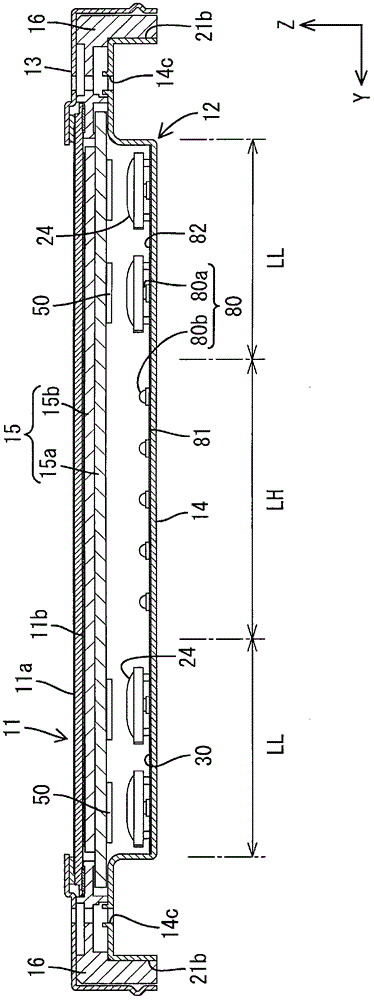
[0105] The backlight device 12 adopted in Embodiment 2 has LED light sources 80 on the LED substrate 81, so that a light source high-density region with relatively close arrangement intervals of the LED light sources 80 is formed at the central portion of the LED substrate 81 (that is, the central portion of the chassis 14). LH is arranged on the LED substrate 81 in such a manner that the light source low-density region LL in which the LED light sources 80 are arranged at a relativel...


PUM

PropertyMeasurementUnit
reflectivityaaaaaaaaaa

Abstract

The invention aims to provide a lighting device which suppresses the occurrence of a lamp image while achieving reductions in cost and power consumption. Specifically disclosed is a lighting device (12) characterized by being provided with a plurality of point light sources (80), a chassis (14) housing the point light sources (80) and having an opening (14b) for emitting light of the point light sources (80), and an optical member (15 (15a)) facing the point light sources (80) and disposed so as to cover the opening (14b), wherein the point light sources (80) are disposed so as to form a light source high-density region (LH) in which the point light sources are relatively densely disposed and a light source low-density region (LL) in which the point light sources are relatively sparsely disposed, and a light reflection part (50) for reflecting light from the point light source (80); is formed in a portion overlapping with at least the light source low-density region (LL) of the optical member (15 (15a)).

Description

technical field [0001] The present invention relates to an illuminating device, a display device and a television receiving device. Background technique [0002] For example, a liquid crystal panel used in a liquid crystal display device such as a liquid crystal television does not emit light by itself, so a backlight device is separately required as an illumination device. It is well known that the backlight device is arranged on the back side (the side opposite to the display surface) of the liquid crystal panel, and it is provided with: a base, which has an opening on the side of the liquid crystal panel; a plurality of light sources (such as LEDs), which serve as The lamp is housed in the chassis, and the optical member (diffuser plate, etc.) is arranged in the opening of the chassis to efficiently radiate light from the light source toward the liquid crystal panel. [0003] Such a backlight device has a configuration in which the in-plane luminance of illumination ligh...

Claims


Application Information

Patent Timeline
Patent Type & Authority Applications(China)
IPC IPC(8): F21S2/00G02F1/13357H04N5/66F21Y101/02
CPCG02F1/133603G02F1/133611G02F2001/133613G02F2001/133607G02F1/133605G02F1/133613G02F1/133607
Inventor 横田匡史
Owner SHARP KK
Why Eureka
Try Eureka