
Asymmetric capacitance and resistance increasing and injecting method of zero-sequence current

An asymmetric capacitor and zero-sequence current technology, which is applied in the direction of measuring current/voltage, measuring electrical variables, instruments, etc., can solve the problems of small injected energy, difficult line selection and positioning, etc., so as to increase the current amplitude and avoid the effect of shunting Effect

Inactive Publication Date: 2012-11-28
CHINA PETROLEUM & CHEM CORP +1
View PDF1 Cites 0 Cited by
  • Summary
  • Abstract
  • Description
  • Claims
  • Application Information

AI Technical Summary

Problems solved by technology

[0005] The purpose of the present invention is to provide an asymmetric capacitance and resistance injection method for zero-sequence current, to solve the problem that the injection energy of the line selection and positioning device composed of the principle of "injection method" is too small, and the problem of difficult line selection and location is difficult

Method used


Image

  • Asymmetric capacitance and resistance increasing and injecting method of zero-sequence current
  • Asymmetric capacitance and resistance increasing and injecting method of zero-sequence current
  • Asymmetric capacitance and resistance increasing and injecting method of zero-sequence current

Examples


Embodiment 1

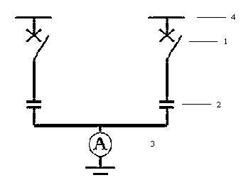
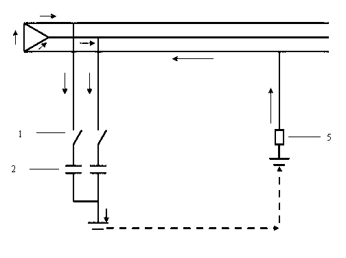
[0019] See figure 1 , the asymmetric capacitance injection method is to connect the upper terminal of the high-voltage vacuum contactor 1 with the three-phase power bus 4 of the substation, and connect the lower terminal of the high-voltage vacuum contactor 1 with the upper terminal of the high-voltage capacitor 2 of the non-fault phase, The lower terminals of the non-fault phase high-voltage capacitor 2 are connected to each other and then connected to the upper terminal of the ammeter 3, and the lower terminal of the ammeter 3 is connected to the ground. Will figure 1 The non-fault phase high-voltage capacitor 2 is connected to the three-phase power bus 4 through the high-voltage vacuum contactor 1, for example, connected to the 10 KV three-phase power bus, so that the injected current flows through the non-fault phase high-voltage capacitor 2 under the action of the power supply voltage and the transition resistance 5 of the grounding point, by adjusting the size of the ...

Embodiment 2

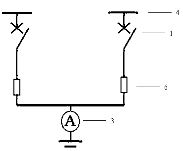
[0021] See figure 2 , the asymmetric resistance injection method is to connect the upper terminal of the high-voltage vacuum contactor 1 with the three-phase power bus 4 of the substation, and connect the lower terminal of the high-voltage vacuum contactor 1 to the upper terminal of the non-faulty phase resistance 6. The lower terminals of the faulty phase resistance 6 are connected to each other and then connected to the upper terminal of the ammeter 3, and the lower terminal of the ammeter 3 is connected to the ground. Will figure 2 The non-fault phase resistor 6 is connected to the three-phase power bus 4 through the high-voltage vacuum contactor 1, for example, connected to the 10KV three-phase power bus, so that the injection current flows through the non-fault phase resistor 6 and the grounding point under the action of the power supply voltage The transition resistance 5 is adjusted by adjusting the size of the non-fault phase resistance 6 . The purpose of increasing ...


PUM


Abstract

The invention discloses an asymmetric capacitance and resistance increasing and injecting method of zero-sequence current, which is an asymmetric zero-sequence current injecting method used in a neutral point ungrounded system, wherein switching of a healthy-phase high-voltage capacitor or a healthy-phase resistor is controlled by connecting a high-voltage vacuum contactor with the bus of a three-phase power supply; and the value of current flowing through a fault point is increased by injecting grounded current through the healthy-phase high-voltage capacitor or the healthy-phase resistor and adjusting the resistance of the healthy-phase high-voltage capacitor or the healthy-phase resistor, so that the amplitude of fault electric capacity is increased. Compared with the three-phase synchronous injecting method adopted in the prior art, the shunting action of capacitance corresponding to faults on injection amount is avoided; therefore, all the injection amount flows through the fault point; and the problem that the injection current value is restricted by zero-sequence voltage of a power distribution network system is solved.

Description

technical field [0001] The invention relates to a grounding fault detection method in a power system, in particular to an asymmetric capacitance and resistance injection method for zero-sequence current, and is an asymmetric zero-sequence current injection method used in a neutral point ungrounded system. Background technique [0002] In the power system, according to the grounding method, it can be divided into a large current grounding system and a small current grounding system. The small current grounding system includes high resistance grounding, arc suppression coil grounding and no grounding. In our country, most of the 3~66kV power system adopts the operation mode that the neutral point is not grounded or grounded through the arc suppression coil, that is, the small current grounding system. The small current grounding system, especially the small grounding system of 35KV and below, has a high probability of single-phase grounding faults during operation due to the ...

Claims


Application Information

Patent Timeline
Patent Type & Authority Applications(China)
IPC IPC(8): G01R31/08G01R19/00
Inventor 杨勤生高志鹏朱玉波赵恒石智利
Owner CHINA PETROLEUM & CHEM CORP
Learn More