Methanol converter synthetic multipoint thermocouple
A converter and thermocouple technology, applied to thermometers, instruments, scientific instruments, etc. that use electric/magnetic elements that are directly sensitive to heat, can solve problems such as low reliability and low measurement accuracy of a single temperature measuring core , to achieve the effect of improving measurement accuracy, facilitating popularization and application, and ensuring consistent orientation
- Summary
- Abstract
- Description
- Claims
- Application Information
AI Technical Summary
Problems solved by technology
Method used
Image
Examples
Embodiment 1
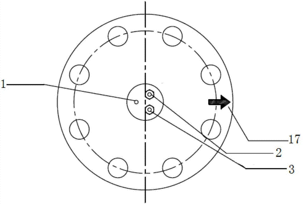
[0042] A synthetic multi-point thermocouple for a methanol converter, comprising a first armored core 2, a second armored core 3, a flange 8, a flange neck 10, a pipe welding joint 11, a joint 12, and a line connection part 13. Ferrule bolt 14, gasket 15, hard gasket 16;
[0043] The flange 8, the flange neck 10, the pipe welding joint 11, and the joint 12 are sequentially connected end to end to form a fixed member, and the first armored core 2 and the second armored core 3 pass through the fixed member, and The end portions of the first armored core body 2 and the second armored core body 3 are connected with a line connection part 13, and the first armored core body 2 and the second armored core body 3 are connected to the electrical box through the line connection part 13, so The first armored core body 2 and the second armored core body 3 are respectively arranged in the joint 12 through ferrule bolts 14, and the first armored core body 2 and the second armored core body ...
Embodiment 2
[0050]This embodiment is improved on the basis of Embodiment 1, the support rod 1, the first armored core body 2, and the second armored core body 3 are arranged in parallel, and a plurality of support rings 5 connect the first armored core body 2 , the second armored core body 3 is fixed on the support rod 1, so that it maintains a straight line structure parallel to each other, preventing the first armored core body 2 and the second armored core body 3 from being screwed together, the support ring 5 The edge position of the guide notch 5-2 is provided, and the first hole 5-1, the second hole 5-3, the third hole 5-4, and the center of the third hole 5-4 are provided on the support ring 5. Located on the vertical line connecting the center of the first hole 5-1 and the center of the second hole 5-3, the symmetry line of the guide notch 5-2 is located at the center of the first hole 5-1 and the center of the second hole 5-3. On the vertical line of the line, the first hole 5-...
Embodiment 3
[0057] This embodiment is improved on the basis of Embodiment 2. The distance between any two adjacent temperature measuring points 4 on the first armored core body 2 and the second armored core body 3 is the same, which is 1210mm. .
[0058] The guide notch 5-2 is a semicircular hole.
[0059] A thermal insulation layer 6 is covered between the two support rings 5 on the left and right sides of any temperature measuring point 4 .
[0060] The first armored core body 2 and the second armored core body 3 are provided with ten temperature measuring points 4, and fifty supporting rings 5 are arranged on the temperature measuring core body, and two adjacent temperature measuring points Five supporting rings 5 are arranged between the 4.
[0061] The heat insulating layer 6 adopts ceramic fibers.
[0062] The distance between two adjacent temperature measurement points 4 is 1210mm, the distance between any temperature measurement point 4 and the support ring 5 on the left ...
PUM
 Abstract
Description
Claims
Application Information
 - R&D Engineer
- R&D Manager
- IP Professional
- Industry Leading Data Capabilities
- Powerful AI technology
- Patent DNA Extraction
Browse by: Latest US Patents, China's latest patents, Technical Efficacy Thesaurus, Application Domain, Technology Topic, Popular Technical Reports.
© 2024 PatSnap. All rights reserved.Legal|Privacy policy|Modern Slavery Act Transparency Statement|Sitemap|About US| Contact US: help@patsnap.com


