Movable refuse incinerator
A waste incinerator, mobile technology, applied in incinerators, combustion methods, combustion types, etc., can solve problems such as large investment in waste volume
Inactive Publication Date: 2012-11-21
黄时峰
View PDF5 Cites 2 Cited by
- Summary
- Abstract
- Description
- Claims
- Application Information
AI Technical Summary
Problems solved by technology
Landfill needs to occupy a certain land area, and the landfill site needs to be far away from the places where people live; while the current incineration methods and technologies require a large investment and a certain amount of garbage, which is very important for decentralized collection and miniaturization of treatment. The current landfill and incineration methods are unable to adapt to household waste management in rural areas.
Method used
View moreImage
Smart ImageViewing Examples

Examples
Embodiment 1
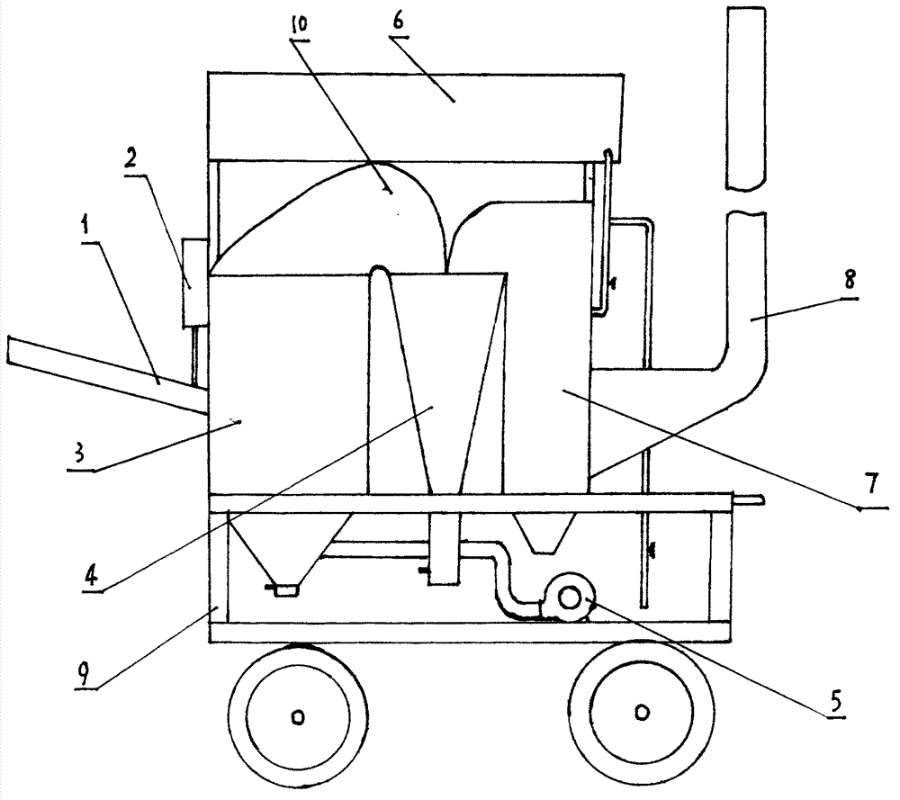
[0015] Example 1: After the miniaturization design and processing of conventional mature technology, the machine is sequentially connected to the feed chute 1, the feed control system 2, the combustion system 3, the air supply system 5, the dust collection system 4, and the water spray system 6 , the water vaporization system 7, and the garbage disposal system 10 formed by the chimney 8 are integrally installed on the walking system 9.
Login to View More PUM
 Abstract
The invention discloses a movable refuse incinerator. The movable refuse incinerator is formed in the manner that a refuse disposal system (10) formed by mechanically connecting a feed chute (1), a feed control system (2), a combustion system (3), an air supply system (5), a dust collection system (4), a water spray system (6), a water vaporization system (7) and a chimney (8) in sequence is integrally arranged on a running system (9). As the mature technology is adopted by all systems and all the systems are arranged on the running system (9) after being miniaturized, the movable refuse incinerator can be dragged to scattered refuse disposal sites by using a trailer to perform refuse incineration disposal. The movable refuse incinerator is especially suitable for rural refuse collection decentralization, disposal miniaturization and management domestication and is suitable for flow incineration disposal of rural household refuse.
Description
technical field [0001] The present invention relates to a kind of garbage treatment equipment, more specifically, the invention relates to a kind of garbage incineration equipment. Background technique [0002] my country has now entered the period of new rural construction. In the process of new rural construction, road construction has been completed, communication facilities have been completed, rural electricity consumption has been solved, housing renovation has revealed the vigorous vitality of rural areas, and the improvement of rural environmental sanitation conditions has also been put on the agenda. [0003] The most important thing to improve the sanitation conditions in rural areas is the treatment of rural domestic waste. With the improvement of living standards in rural areas, like cities, a large amount of domestic garbage has appeared in rural areas. Plastic bottles, packaging boxes, plastic food bags, and rotten food can be seen everywhere, which greatly af...
Claims
Login to View More Application Information
Patent Timeline
 Patent Type & Authority Applications(China)
IPC IPC(8): F23G5/40F23G5/44
Inventor 黄时峰
Owner 黄时峰
Features
- Generate Ideas
- Intellectual Property
- Life Sciences
- Materials
- Tech Scout
- Unparalleled Data Quality
- Higher Quality Content
- 60% Fewer Hallucinations
Learn More Browse by: Latest US Patents, China's latest patents, Technical Efficacy Thesaurus, Application Domain, Technology Topic, Popular Technical Reports.
© 2025 PatSnap. All rights reserved.Legal|Privacy policy|Modern Slavery Act Transparency Statement|Sitemap|About US| Contact US: help@patsnap.com