Exhaust gas purification device and temperature control method thereof

A technology of exhaust gas purification device and temperature control method, which is applied in the direction of combustion method, controlled combustion, incinerator, etc. It can solve the problems of temperature drop, VOC cannot decompose exhaust gas, exhaust gas temperature rise, etc., and achieve the effect of preventing temperature drop

Active Publication Date: 2015-07-29
SINTOKOGIO LTD
View PDF7 Cites 0 Cited by
  • Summary
  • Abstract
  • Description
  • Claims
  • Application Information

AI Technical Summary

Problems solved by technology

In this way, when a plurality of exhaust gas generation sources are connected to one exhaust gas purification device, there is a problem that the temperature of the combustion chamber of the exhaust gas purification device may drop and the exhaust temperature of the exhaust gas may rise abnormally.
This pr

Method used


Image

  • Exhaust gas purification device and temperature control method thereof
  • Exhaust gas purification device and temperature control method thereof
  • Exhaust gas purification device and temperature control method thereof

Examples


Embodiment Construction

[0030] Next, an exhaust gas purification device and a temperature control method thereof according to an embodiment of the present invention will be described with reference to the drawings. In the following description, "set value (target value)" may be described as "SP (Set Point)".

[0031] First, use Figure 1~Figure 5 , the exhaust gas purification device and the temperature control method thereof according to the first embodiment of the present invention will be described.

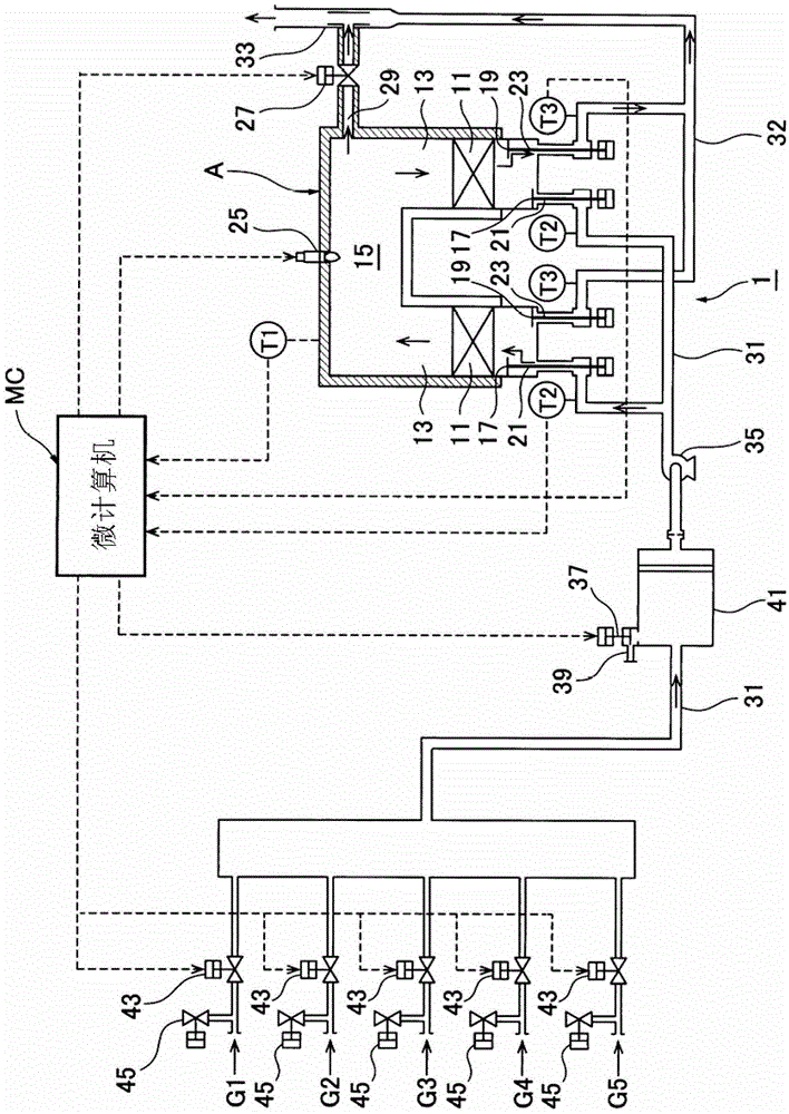
[0032] figure 1 The two-tower exhaust gas purification device 1 according to the first embodiment of the present invention is shown. This exhaust gas purification device 1 includes a plurality (two in the illustration) of regenerators 13 in which regenerators 11 are provided, and a combustion chamber 15 formed to communicate with the upper side of the plurality of regenerators 13 , 13 . Here, the heat storage body 11 is a honeycomb ceramic.

[0033]The regenerator 13 is provided with an air supp...


PUM


Abstract

The present invention is an exhaust gas purification device (1, 501) for purifying exhaust gas containing a combustible toxic component. This exhaust gas purification device comprises a plurality of heat storage chambers (13) which are each provided with a heat storage element (11) therein and provided with a pair of an air supply port and an air evacuation port (21, 23), a combustion chamber (15) which is formed to communicate with the upper parts of the plurality of heat storage chambers, air evacuation and air supply valves (17, 19) which are mounted to the air supply port and the air evacuation port of each of the heat storage chambers in order to perform switching between the supply of air to and the evacuation of air from the heat storage chamber, a heating burner (25) which is provided in the combustion chamber, a heat discharge damper (27) which discharges surplus heat from the combustion chamber, and a microcomputer (MC) which ignites/extinguishes the heating burner on the basis of a combustion chamber temperature (t1) and controls the temperature such that the combustion chamber temperature becomes a set value (SP) by adjusting the degree of opening of the heat discharge damper. This microcomputer determines whether early combustion, in which the temperature of exhaust gas rises to a self-burning temperature or higher when the exhaust gas passes the heat storage element, and the exhaust gas burns before arriving at the combustion chamber, is performed or not, when determining that the early combustion is performed, executes an early combustion countermeasure operation for forcibly opening the heat discharge damper and extinguishing the heating burner, and thereafter when determining that the early combustion is not performed, cancels the early combustion countermeasure operation.

Description

technical field [0001] The invention relates to a waste gas purification device and a temperature control method for purifying waste gas containing combustible harmful components. Background technique [0002] Conventionally, as described in Japanese Patent Laid-Open No. 2004-77017, an exhaust gas purification device has been used in the purification treatment of exhaust gas containing waste from binder use, printing, painting, organic solvent cleaning facilities, chemical factories, etc. Combustible and toxic components such as volatile organic compounds (VOC: Volatile Organic Compound) produced. [0003] The exhaust gas purifying device includes, for example, a plurality of heat storage chambers, each of which has a pair of air supply ports equipped with an air supply valve and exhaust ports equipped with an exhaust valve, and a heat storage body is provided therein. A combustion chamber communicating with the upper side of these regenerators is also provided. In this re...

Claims


Application Information

Patent Timeline
IPC IPC(8): F23G7/06F23L15/02F23N5/00
CPCF23G5/50F23G7/068Y02P80/15
Inventor 尾崎照彦大木佳彦鸟田智弘佐野道尚
Owner SINTOKOGIO LTD
Why Eureka
Try Eureka