
Piston cooling device

A piston cooling and piston technology, which is applied in the direction of piston, liquid cooling, engine cooling, etc., can solve the problem that the engine oil is not supplied, and achieve the effect of reducing pressure loss, improving cooling efficiency, and realizing cooling efficiency

Inactive Publication Date: 2012-11-14
HONDA MOTOR CO LTD
View PDF7 Cites 3 Cited by
  • Summary
  • Abstract
  • Description
  • Claims
  • Application Information

AI Technical Summary

Problems solved by technology

[0004] In addition, when the internal combustion engine rotates at high speed, if the speed of the reciprocating piston becomes higher than the speed of the oil injected from the oil injector, there will be a period in which the oil is not supplied to the cooling passage of the piston.

Method used


Image

  • Piston cooling device
  • Piston cooling device
  • Piston cooling device

Examples


Embodiment Construction

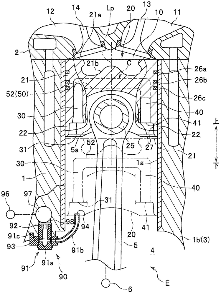
[0045] Below, refer to Figure 1 to Figure 7 Embodiments of the present invention will be described.

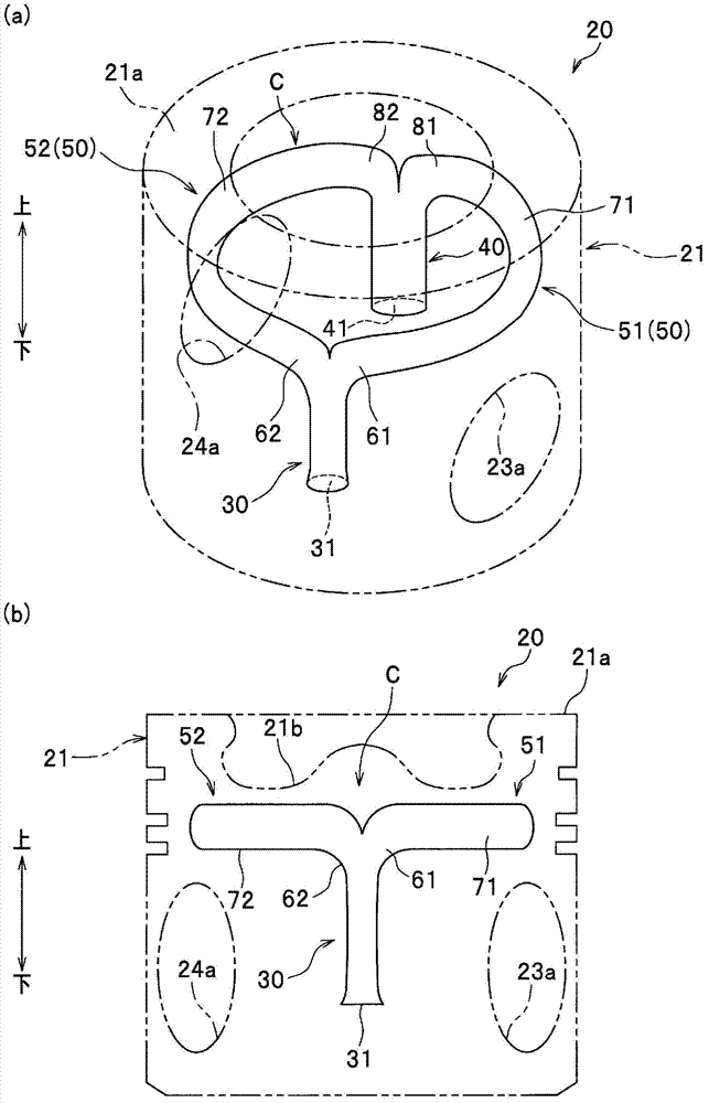
[0046] Figure 1 to Figure 5 It is a figure for demonstrating the 1st Embodiment of this invention.

[0047] refer to figure 1 , the internal combustion engine E provided with the piston cooling device to which the present invention is applied is a 4-stroke internal combustion engine. The internal combustion engine E has an internal combustion engine main body composed of: a cylinder block 1 provided with a cylinder bore 1a in which a piston 20 for an internal combustion engine is reciprocally fitted; The upper end of the cylinder block 1 is connected; an oil pan (not shown) is connected to the lower end of the cylinder block 1 via a lower block (not shown).

[0048] In the cylinder block 1 , a portion 1 b below the cylinder bore 1 a serves as an upper crankcase, and constitutes a crankcase 3 together with a lower crankcase composed of the lower spacer and the oil pan. I...


PUM


Abstract

Disclosed is a piston cooling device wherein the cooling efficiency of a piston is improved by oil injected from an oil jet and supplied to a cooling passage provided in the piston, and the amount of cooling oil is reduced when an internal combustion engine is operated at maximum output. The piston cooling device is provided with a piston (20) for an internal combustion engine, in which a circumferential passage (50) and a cooling passage (C) having an inlet passage (30) and an outlet passage (40) are provided, and an oil jet (90) for injecting oil from an injection port (94) to the inlet passage (30). The oil jet (90) injects oil at every stroke of the piston (20) so that a two-phase plug flow composed of gas and oil is formed in the cooling passage (C) at least when an internal combustion engine (E) is operated at maximum output. The injection speed of oil at the injection port (94) is not higher than the maximum speed of the piston (20) when the internal combustion engine is operated at maximum output.

Description

technical field [0001] The present invention relates to a piston cooling device that supplies oil injected from an oil injector to a cooling passage provided in a piston of an internal combustion engine, and cools the piston with the oil flowing through the cooling passage. Background technique [0002] With the increase in output of internal combustion engines, it is known to supply cooling oil injected from an oil injector to a ring provided inside the piston in order to cool the piston head having the piston top surface in contact with the combustion gas in the piston. Piston cooling device with shaped cooling channels. [0003] For example, in the piston cooling device disclosed in Patent Document 1, a guide portion is provided that guides the oil injected from the oil injector into the circumferential passage of the cooling passage of the piston, thereby improving the cooling efficiency. . [0004] Also, when the internal combustion engine rotates at high speed, if th...

Claims


Application Information

Patent Timeline
Patent Type & Authority Applications(China)
IPC IPC(8): F01M1/08
CPCF01P3/10F01P3/06F01P3/08F02F3/22F01M1/08F01P2003/006
Inventor 圆山重直小宫敦树守谷修一长田守正小坂诚二河村康宏根岸润也塚本能人
Owner HONDA MOTOR CO LTD
Learn More