Push screw device and roll forming machine

A screw and moving roller technology, applied in the field of roll forming machines, can solve the problems of easy adhesion of raw materials or retention of scoop shells, overload and other problems

Active Publication Date: 2012-11-14
NIPPON STEEL CORP +1
View PDF7 Cites 3 Cited by
  • Summary
  • Abstract
  • Description
  • Claims
  • Application Information

AI Technical Summary

Problems solved by technology

[0015] However, even in the push-in screw disclosed in Patent Document 4, the raw material tends to adhere to or remain on the inner wall of the bucket shell. In order to scrape off the raw material adhered to the inner wall of the shell, the push-in screw provided at both ends become an overload concern

Method used


Image

  • Push screw device and roll forming machine
  • Push screw device and roll forming machine
  • Push screw device and roll forming machine

Examples


Embodiment Construction

[0031] A press-in screw device for a briquette machine (hereinafter referred to as a press-in screw device) according to an embodiment of the present invention and a briquette machine (roll former) equipped with the same will be described below with reference to the drawings.

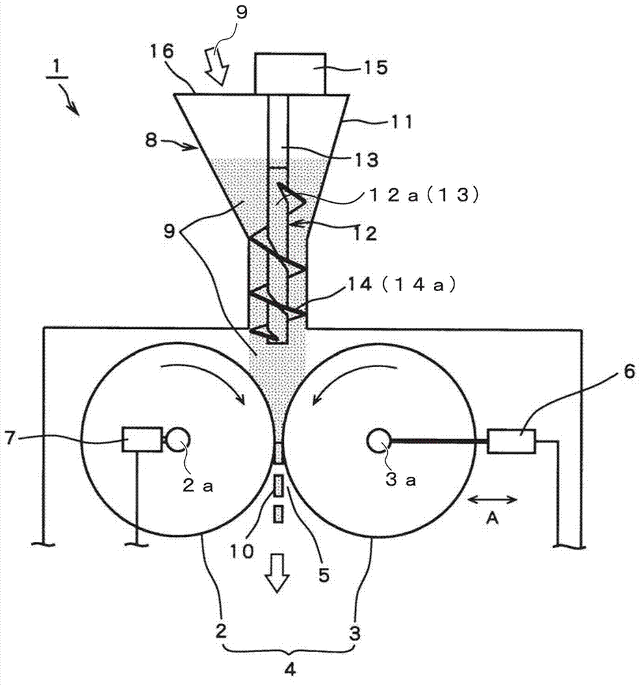
[0032] figure 1 It is a vertical cross-sectional view showing a schematic structure of the briquette machine 1 of the present embodiment.

[0033] This briquetting machine 1 is provided with: a casing 11 for storing raw materials 9 and a bucket 8 for pressing the raw materials 9 in the casing 11 to the lower part of the screw device 12, and by sandwiching the raw material 9 extruded from the bucket 8, The raw material 9 is a pair of fixed roll 2 and movable roll 3 for press molding.

[0034] The fixed roll 2 and the movable roll 3 of this briquette machine 1 have rotating shafts 2 a and 3 a parallel to each other in the horizontal direction, respectively, and rotate inwards of each other in plan view....


PUM


Abstract

Disclosed is a push screw device wherein: each push screw is arranged such that each rotationally driving shaft is disposed along the same straight line when viewed from above; the bottom end position in the vertical direction of each screw blade is the same and the spiral winding direction of these screw blades is opposite for adjacent screw blades; two push screws disposed at the center of the arranged direction of the push screws are the center screws, and the rotation direction of the screw blades and the supply direction of the raw material is the same, when the section between each of the rotationally driving shafts that contain these center screws is viewed from above.

Description

technical field [0001] The present invention relates to a pressing screw device suitable for use in a roll forming machine for pressing a raw material mixed with a fine powder and a binder into a plate shape, for example, and a roll forming machine equipped with the pressing screw device. [0002] This application claims the priority based on Japanese Patent Application No. 2010-095648 for which it applied to Japan on April 19, 2010, and uses the content here. Background technique [0003] Conventionally, as an apparatus for press-molding granulated raw materials obtained by mixing fine powder and a binder, a briquetting machine (Roll block forming machine) has been used. briquetting machine such as Figure 4 Shown is a forming roll 104 having a pair of fixed rolls 102 and movable rolls 103 having independent rotation axes. The fixed roller 102 is arranged in a fixed position. On the other hand, the movable roller 103 receives a predetermined pressure from the hydraulic cy...

Claims


Application Information

Patent Timeline
Patent Type & Authority Applications(China)
IPC IPC(8): B30B11/00B30B11/18B65G65/46
CPCB30B15/308B30B11/00B30B11/18B65G65/46
Inventor 真田辉男藤川秀树后藤顺
Owner NIPPON STEEL CORP
Why Eureka
Try Eureka