A two-phase flow dynamic heat pipe system
A fluid power, two-phase flow technology, applied in the field of heat exchange, can solve the problems of incomplete gas-liquid separation, insufficient circulation power, etc., to solve the problems of high and low position difference and conveying distance, reduce the limitation of use conditions, and achieve stability. Effect
- Summary
- Abstract
- Description
- Claims
- Application Information
AI Technical Summary
Problems solved by technology
Method used
Image


Examples
Embodiment 1
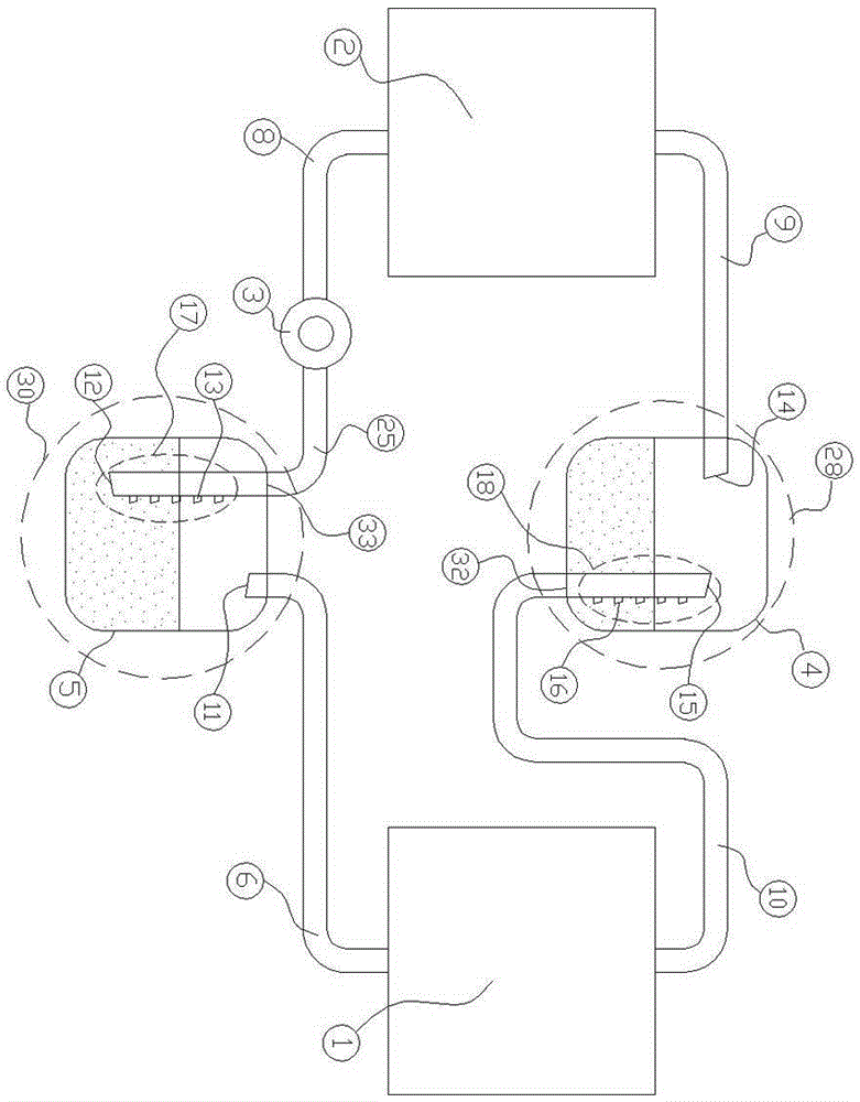
[0028] This embodiment is the workflow of the first implementation mode, such as figure 2 As shown, the condenser (1), circulation pump (3), one-way two-phase flow stabilizer two (30), evaporator (2) and one-way two-phase flow stabilizer one (28) are connected in the above order through the connecting pipes It is connected as a whole to form a one-way two-phase flow dynamic heat pipe circulation system. When the system is working, the condenser (1) is in contact with a low-temperature heat source, and the gaseous working medium is cooled by the low-temperature heat source in the condenser (1) and condenses into a liquid. And release heat, the liquid working medium formed by condensation is driven by the delivery pump (3), and they enter the one-way two-phase current stabilizer two (30 ) of the gas-liquid separator two (5), the gas-liquid two-phase flow intermediate working medium is separated in the gas-liquid separator two (5) according to their respective physical propertie...
Embodiment 2
[0033] This embodiment is the workflow of the second second implementation mode, such as image 3 As shown, the one-way two-phase flow stabilizer two (30) is located between the condenser (1) and the circulating pump (3), and the evaporator (2) and the circulating pump (3) are directly connected by the two-phase The flow input pipe (8) is connected, so that the condenser (1), one-way two-phase flow regulator two (30), circulation pump (3), evaporator (2) and one-way two-phase flow regulator one (28) The connecting pipes are connected as a whole in the above order to form a unidirectional two-phase flow power heat pipe circulation system.
[0034] When the system is working, the circulating pump (3) extracts a certain proportion of two-phase flow working medium from the gas-liquid separator two (5) of the one-way two-phase flow stabilizer two (30), so that the liquid intermediate medium passes through the return liquid Port 1 (12) and a small amount of gaseous intermediate med...
Embodiment 3
[0035] Example 3: In a specific environment, in order to exchange the functions of the condenser (1) and the evaporator (2) in the system, that is, the condenser (1) acts as an evaporator, and the evaporator (2) acts as a condensation The function of the device is improved on the basis of the first embodiment.
[0036] The circulating pump (5) is changed from a unidirectional circulating pump to a bidirectional power motor system (such as a Roots motor) that can directly change direction. The design is the same, and they can be interchanged by inversion. The simple structure diagram of this embodiment is as follows image 3 shown.
[0037] In this system, when the condenser (1) and the evaporator (2) play a normal role, the specific working method is the same as that of Example 1, and its startup and operation process is the same as that of Example 1; when the condenser (1) acts as an evaporator When the evaporator (2) acts as a condenser, its start-up and operation process ...
PUM
 Abstract
Description
Claims
Application Information
 - R&D
- Intellectual Property
- Life Sciences
- Materials
- Tech Scout
- Unparalleled Data Quality
- Higher Quality Content
- 60% Fewer Hallucinations
Browse by: Latest US Patents, China's latest patents, Technical Efficacy Thesaurus, Application Domain, Technology Topic, Popular Technical Reports.
© 2025 PatSnap. All rights reserved.Legal|Privacy policy|Modern Slavery Act Transparency Statement|Sitemap|About US| Contact US: help@patsnap.com