Backflow-preventing pipe joint

A technology of pipe joints and heads, which is applied in the field of pipe joints, can solve the problems of limited installation space of pipe joints, and achieve the effects of simple structure, easy production and processing, and convenient installation

Inactive Publication Date: 2012-11-14
NINGBO JIACHENG HYDRAULIC
View PDF6 Cites 1 Cited by
  • Summary
  • Abstract
  • Description
  • Claims
  • Application Information

AI Technical Summary

Problems solved by technology

However, in specific applications, due to the fixed design size of the equipment / system where the pipe joint itself is located, the installation space provided for the pipe joint is very limited, especially in the oil circuit system of the vehicle and the precision hydraulic system

Method used


Image

  • Backflow-preventing pipe joint
  • Backflow-preventing pipe joint
  • Backflow-preventing pipe joint

Examples


Embodiment 1

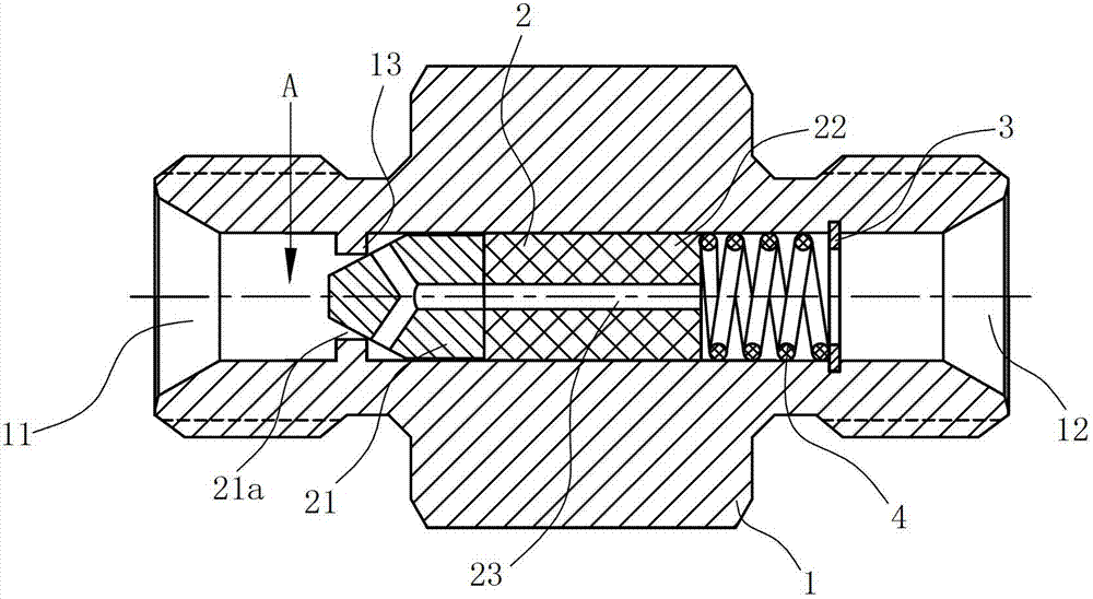
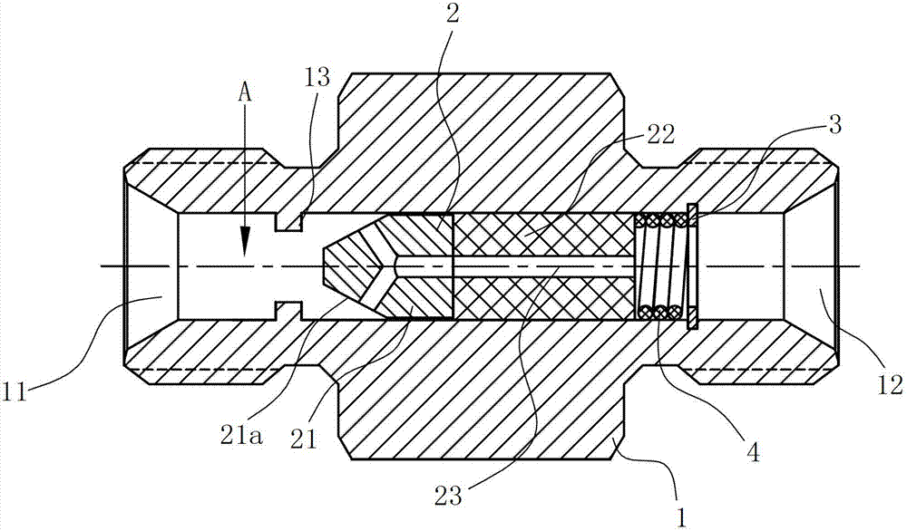
[0018] Such as figure 1 , figure 2 As shown, the pipe joint capable of preventing backflow of the present invention is a two-way joint in this embodiment, including a joint body 1, and the joint body 1 is provided with an inlet port 11 and an outlet port 12, and the inlet port 11 and the outlet port 12 A channel A through the joint body 1 is formed between them,

[0019] A spool 2 that can be limitedly moved along the channel A is provided in one of the channels A, and the spool 2 includes a head 21 facing the inlet end 11 and a tail 22 facing the outlet end 12;

[0020] A snap ring 3 is arranged behind the tail portion 22 of the spool 2 in the passage A, and a spring 4 is tightly pressed between the tail portion 22 of the spool 2 and the snap ring 3;

[0021] The head 21 of the valve core 2 has a conical outer wall 21a, and the inside of the valve core 2 has a flow hole 23 communicating with its conical outer wall 21a and the tail portion 22. The cross section of the flow ...

Embodiment 2

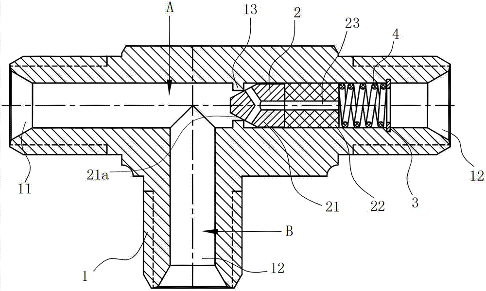
[0025] Such as Figure 3 ~ Figure 4 Shown is the second embodiment of the present invention, which differs from the first embodiment in that: in this embodiment, the pipe joint is a three-way joint, that is, the joint body 1 is provided with two outlet ports 12, Two passages A, B are formed between the inlet port 11 and the two outlet ports 12, and the valve core 2 is arranged in one of the passages A.


PUM


Abstract

The invention relates to a backflow-preventing pipe joint, comprising a joint body (1), wherein the joint body (1) is provided with an inlet end (11), an outlet end (12) and at least one channel (A); a valve spool (2) is arranged inside the channel (A); a clamping ring (3) is arranged behind the tail (22) of the valve spool (2) inside the channel (A), and a spring (4) is tightly abutted between the tail (22) and the clamping ring (3); the head (21) of the valve spool (2) is provided with a conical external wall (21a); and the inner part of the valve spool (2) is provided with a flow hole (23), and a circle of convex ring (13) is arranged at the head (21) of the valve spool (2) on the internal wall of the channel (A). Compared with the prior art, the conical external wall of the valve spool in the pipe joint and the convex ring on the channel form a sealed structure, so that liquid at the outlet end does not flow to the inlet end via the flow hole of the valve spool, the liquid at the outlet end is prevented from back-flowing to the inlet end, and the function of a one-way valve is realized without an external one-way valve; and moreover, the peripheral size of the pipe joint is not increased and the pipe joint is conveniently installed in a narrow equipment space.

Description

technical field [0001] The invention relates to a pipe joint, in particular to a pipe joint capable of preventing backflow. Background technique [0002] Pipe joints are widely used in the connection of oil and liquid transportation pipelines, such as two-way joints, three-way joints, multi-way joints, etc. In order to prevent backflow in a certain channel, a check valve needs to be separately installed on a specific inlet of the pipe joint to achieve the purpose of controlling one-way opening of the flow channel. However, in specific applications, due to the fixed design size of the equipment / system where the pipe joint itself is located, the installation space available for the pipe joint is very limited, especially in the oil circuit system of the vehicle and the precision hydraulic system. Therefore, the existing design of another one-way valve needs to be further improved. Contents of the invention [0003] The technical problem to be solved by the present invention...

Claims


Application Information

Patent Timeline
Patent Type & Authority Applications(China)
IPC IPC(8): F16L29/02
Inventor 郑益锋
Owner NINGBO JIACHENG HYDRAULIC
Why Eureka
Try Eureka