Resonant cavity device, and systems and apparatus using the same

A resonant cavity and device technology, applied in the field of lasers, can solve the problems of not being able to realize high-Q-value transfer cavity at the same time, inability to realize broadband high-reflection coating, etc. Achieve the effect of narrowing the laser line width

Inactive Publication Date: 2015-11-25
NAT INST OF METROLOGY CHINA
View PDF3 Cites 0 Cited by
  • Summary
  • Abstract
  • Description
  • Claims
  • Application Information

AI Technical Summary

Problems solved by technology

Due to the limitations of the existing coating technology, this kind of transfer cavity structure cannot realize broadband high reflectivity coating. Therefore, when the output optical frequencies of the two lasers differ greatly, it is impossible to realize the high-Q value transfer cavity of two frequencies at the same time.

Method used


Image

  • Resonant cavity device, and systems and apparatus using the same
  • Resonant cavity device, and systems and apparatus using the same
  • Resonant cavity device, and systems and apparatus using the same

Examples


Embodiment Construction

[0040] In order to make the object, technical solution and advantages of the present invention clearer, the present invention will be further described in detail below in conjunction with specific embodiments and with reference to the accompanying drawings.

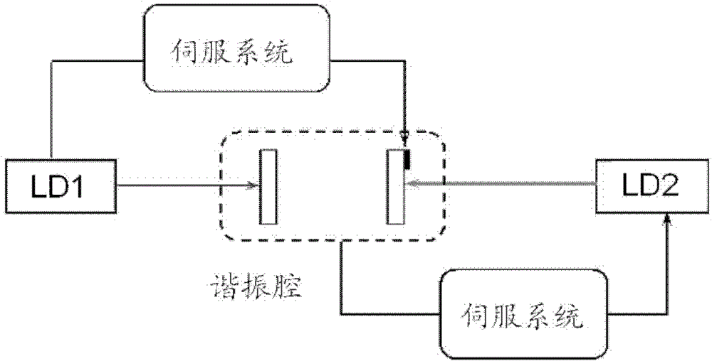
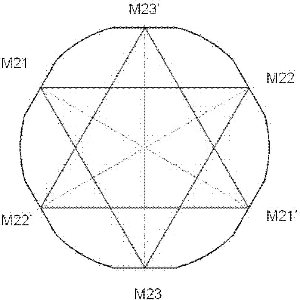
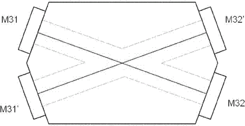
[0041] An embodiment of the present invention provides a resonant cavity device. In the device, multiple optical reflective surfaces constituting the resonant cavity are arranged on a single substrate. The base is in the shape of a polyhedron. The multiple optical reflective surfaces form at least two independent resonant cavity.

[0042] In this way, by simultaneously setting two or more resonant cavity structures on an integrally fixed optical element, the simultaneous use, comparison, and transfer of lasers with different wavelengths and different Q values ​​can be realized. When the resonant cavity device is applied to a laser, it can well narrow the laser line width and stabilize the output.

[0043]Wherein, the opt...


PUM


Abstract

The invention discloses a resonant cavity device, wherein a resonant cavity is formed by a plurality of optical reflecting surfaces which are arranged on a single substrate and of polyhedral shapes. At least two mutually independent resonant cavities are formed by a plurality of optical reflecting surfaces. In addition, based on the resonant cavity device, the invention also provides a system and for a device which both use the resonant cavity device, the resonant cavity device is used as an optical feedback device for pressing and narrowing the width of a laser ray. With the adoption of the system and the device using the resonant cavity device, the laser has the characteristics of wide narrow ray, stable output, simple operation and the like. In addition, by utilizing the resonant cavity device, the stable transmission of laser frequency is realized, and meanwhile, the stable radio frequency signal output is obtained.

Description

technical field [0001] The invention relates to laser technology, in particular to a resonant cavity device, a system and a device using the resonant cavity. Background technique [0002] Semiconductor lasers are widely used in various fields due to their advantages such as simplicity, compactness, easy operation, low price, and wide spectral coverage. However, the line width of the semiconductor laser is relatively wide, which brings a lot of inconvenience to the application. [0003] In order to obtain a narrow linewidth semiconductor laser, the following methods are commonly used at present: use the method of photoelectric feedback to lock the frequency of the external cavity semiconductor laser on the high-Q F-P cavity, so as to realize the narrowing of the laser linewidth. Through the optical feedback method, the narrow linewidth laser filtered by the resonator is fed back to the laser, and the laser linewidth is narrowed by using the principle of stimulated radiation....

Claims


Application Information

Patent Timeline
Patent Type & Authority Patents(China)
IPC IPC(8): H01S5/10H01S5/068
Inventor 臧二军赵阳李烨曹建平方占军
Owner NAT INST OF METROLOGY CHINA
Why Eureka
Try Eureka