Micro-display slit system and micro-display slit method

A microscopic and fissure technology, applied in microscopes, optics, instruments, etc., can solve the problems of difficult adjustment, complex overall structure, and high manufacturing cost, and achieve the effect of simplified overall structure, simple adjustment operation, and reduced production cost.

Inactive Publication Date: 2012-11-07
SHANGHAI MEDIWORKS PRECISION INSTR CO LTD
View PDF3 Cites 10 Cited by
  • Summary
  • Abstract
  • Description
  • Claims
  • Application Information

AI Technical Summary

Problems solved by technology

[0004] 1. The overall structure is complex, the accuracy of the parts is strict, the production process is difficult, and the manufacturing cost is high
[0005] 2. It is not easy to adjust during installation and use
[0006] 3. The fissure opening adopts the method of rotating and driving around a fixed axis, and sometimes there is a difference between the closing position and the opening position of the fissure blade, resulting in a decrease in the quality of the light spot of the formed fissure image
[0010] At present, there is no slit system and method to overcome the above defects in the market, which can replace and simplify the slit blade system, aperture switching system and color filter switching system of the light source part of the slit lamp as a whole.

Method used


Image

  • Micro-display slit system and micro-display slit method
  • Micro-display slit system and micro-display slit method
  • Micro-display slit system and micro-display slit method

Examples


Embodiment Construction

[0034] The specific embodiment of the present invention will be further elaborated below in conjunction with accompanying drawing:

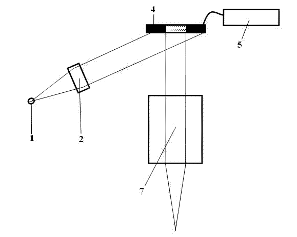
[0035] figure 1 It is a schematic diagram of a digital light processing DLP chip micro-crack implementation system. The micro-display chip 4 uses a digital light processing DLP chip, and the micro-display chip drive unit 5 controls and forms cracks on the micro-display chip 4 . The light emitted by the light source 1 reaches the microdisplay chip 4 after passing through the collimation unit 2, and the array of tiny mirrors in the slit actually becomes a surface light source irradiated by parallel light, and each tiny mirror on it The angle can be controlled by the micro-display chip driving unit 5; the reflection direction of the tiny mirror array of the micro-display chip 4 is controlled by the micro-display chip driving unit 5 to achieve control of whether and how much light passes through the projection unit 7, different crack patterns ar...


PUM


Abstract

The invention discloses a micro-display slit system and a micro-display slit method, relates to the field of optical instruments, and aims to solve the problem that a slit blade of a slit lamp is inconvenient to mount and use. The micro-display slit system comprises a light source (1), a collimating unit (2), a polarizing unit (3), a micro-display chip (4), a micro-display chip drive unit (5), a polarization analysis unit (6), and a projection unit (7). The micro-display chip drive unit (5) drives the micro-display chip (4) to form a slit, a slit blade in an existing slit lamp is replaced, and accordingly the micro-display silt system is simple to mount and use, and regulation of size, shape, light intensity and color of a formed image is more convenient. The micro-display silt system is mainly used for slit lamp microscopes for ophthalmic testing.

Description

technical field [0001] The invention relates to a microscopic slit system and method, in particular to designing a microscopic slit system and method applied to a slit lamp microscope. Background technique [0002] The slit system of the current slit lamp generally uses blade switching to adjust the width of the slit, the length of the slit and the size of the spot are realized through the aperture switching system, and the color change is realized by the color filter switching system. These switching systems require high precision and are difficult to operate during production, installation and use. The manufacturing process is difficult, the cost is relatively high, the size, pattern, color, and brightness of cracks and spots that can be realized are relatively small, and the color scheme is relatively primitive. [0003] The slit system technology of the existing slit lamp specifically has the following defects: [0004] 1. The overall structure is complex, the accurac...

Claims


Application Information

Patent Timeline
IPC IPC(8): G02B21/36G02B21/06
CPCA61B3/135
Inventor 严苏峰魏悦于航陈文光孔昭松
Owner SHANGHAI MEDIWORKS PRECISION INSTR CO LTD
Why Eureka
Try Eureka