Infusion drop monitoring system on basis of sound wave vibration signal
A vibration signal and monitoring system technology, applied in the field of medical equipment, can solve the problems of high machine cost and consumable cost, few applications, and high price, and achieve the effect of simple and practical structure, strong anti-interference ability, and low production cost
- Summary
- Abstract
- Description
- Claims
- Application Information
AI Technical Summary
Problems solved by technology
Method used
Image
Examples
Embodiment 1
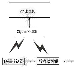
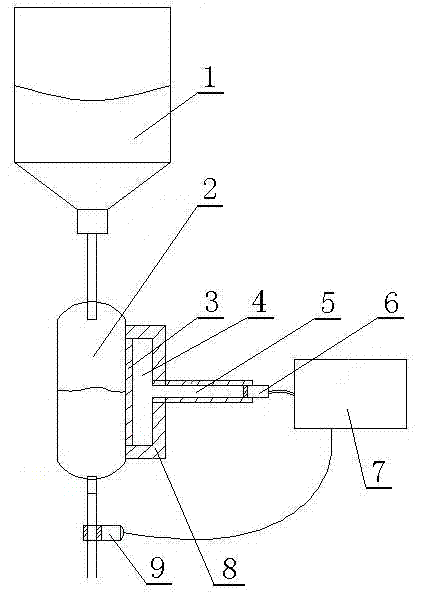
[0023] As shown in the accompanying drawing, the infusion drip monitoring system based on acoustic vibration signals used by a certain hospital includes multiple terminal controllers, ZigBee coordinators and PC host computers; Host computer carries out wireless data transmission; Described terminal controller comprises sound wave signal collector 8, control mainboard 7 and precision step clamping motor 9; The tight contact surface of described sound wave signal collector 8 and Murphy's dropper 2 Diaphragm 3 is set, and acoustic wave signal collector 8 is provided with membrane cavity 4 and cavity 5, and one end of cavity 5 communicates with membrane cavity 4, and the other end is equipped with pickup 6; pickup 6 is connected with control main board 7, and control main board 7 is connected with precision stepping and clamping motor 9 wires; Described control mainboard 7 is provided with data processing module and wireless transmission data module; Described wireless transmission...
Embodiment 2
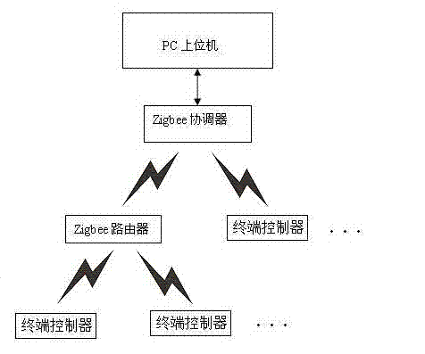
[0025] As shown in the accompanying drawing, the infusion drip monitoring system based on the acoustic vibration signal used by a certain hospital includes a terminal controller, a ZigBee router, a ZigBee coordinator and a PC host computer; Coordinator and PC upper computer carry out wireless data transmission; Described terminal controller comprises sound wave signal collector 8, control mainboard 7 and precision step clamping motor 9; Described sound wave signal collector 8 and Murphy's dropper 2 The diaphragm 3 is arranged on the close contact surface of the acoustic wave signal collector 8, and the cavity 4 and the cavity 5 are arranged in the acoustic wave signal collector 8. One end of the cavity 5 communicates with the cavity 4, and a pickup 6 is installed at the other end; the pickup 6 is connected to the control board 7 Connect, control mainboard 7 is connected with 9 wires of precision step clamping motor; Described control mainboard 7 is provided with data processing...
PUM
 Abstract
Description
Claims
Application Information
 - R&D
- Intellectual Property
- Life Sciences
- Materials
- Tech Scout
- Unparalleled Data Quality
- Higher Quality Content
- 60% Fewer Hallucinations
Browse by: Latest US Patents, China's latest patents, Technical Efficacy Thesaurus, Application Domain, Technology Topic, Popular Technical Reports.
© 2025 PatSnap. All rights reserved.Legal|Privacy policy|Modern Slavery Act Transparency Statement|Sitemap|About US| Contact US: help@patsnap.com


