
Axial vibration-resistant connector

A vibration-resistant, connector technology, applied in the direction of connection, two-part connection device, parts of the connection device, etc., can solve the problems of short-term disconnection, high cost, large volume, etc., and achieve convenient installation or disconnection, contact resistance Small, well adapted to the environment

Inactive Publication Date: 2012-10-31
邹政耀
View PDF3 Cites 0 Cited by
  • Summary
  • Abstract
  • Description
  • Claims
  • Application Information

AI Technical Summary

Problems solved by technology

Taking the DC brushless motor for new energy vehicles as an example, its three Hall elements are connected to the controller with 5 wires, and the signal state changes 6 times when the motor rotates for 1 revolution. When the motor speed is 3000 rpm, its The frequency is 300 Hz, it can be seen that an open circuit of less than 1 millisecond will affect the controller's control of the motor, and even cause damage to electronic components
At present, the crimping method of wires and connector components is used, and the plug and socket of the connector are locked after contact, but short-term disconnection is prone to occur under vibration, which affects the reliability of equipment or components. At the same time, automobiles and rail vehicles run around the clock. The sealing of the connector is not good; the patented product adopts the taper connection, which solves the stability of the connection and quick plug-in and pull-out, but does not solve the problem of one-time plug-in and pull-out of multiple connections; the multi-pin aviation connector has structural advantages. Special locking mechanism, reliable connection, but larger size and higher cost

Method used


Image

  • Axial vibration-resistant connector
  • Axial vibration-resistant connector
  • Axial vibration-resistant connector

Examples


Embodiment Construction

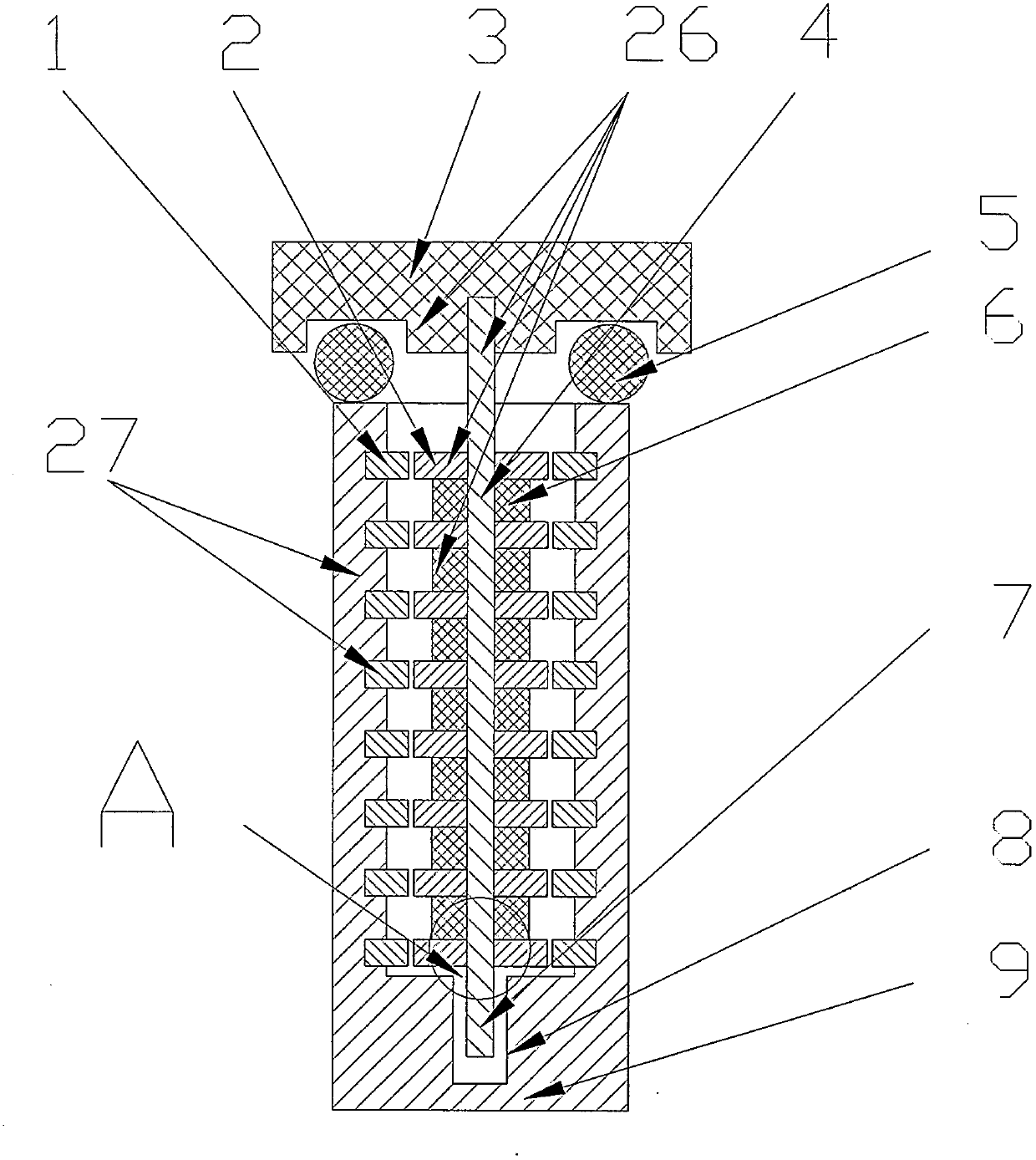
[0021] Refer to attached figure 1 , a shaft-type vibration-resistant connector is characterized in that: the plug shaft group (26) is composed of a plug (2), a plug shaft end cover (3), a plug shaft (4) and an insulating spacer (6), and the plug (2) 8 pieces are set, coaxially fixedly installed on the periphery of the plug shaft (4), and the insulating spacers (6) and the insulating spacers (6) are fixedly installed between the plugs (2) Coaxial fixedly installed on the periphery of the plug shaft (4), the long axis of the plug (2) is 24.4mm, the short axis is 24mm, the thickness is 3mm, the material is red copper, the plug shaft (4) is fixed and installed For the plug shaft end cover (3), the size of the plug shaft (4) is 12mm×12mm×30mm, the material is bakelite, and the socket hole group (27) is composed of a socket (1) and a socket shell (9). The socket (1) is provided with 8 pieces, and the socket (1) is coaxially fixedly mounted on the socket shell (9), and the bottom of...


PUM


Abstract

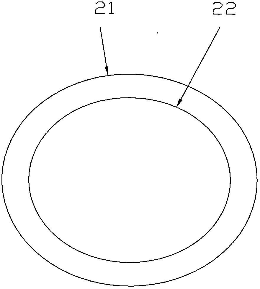
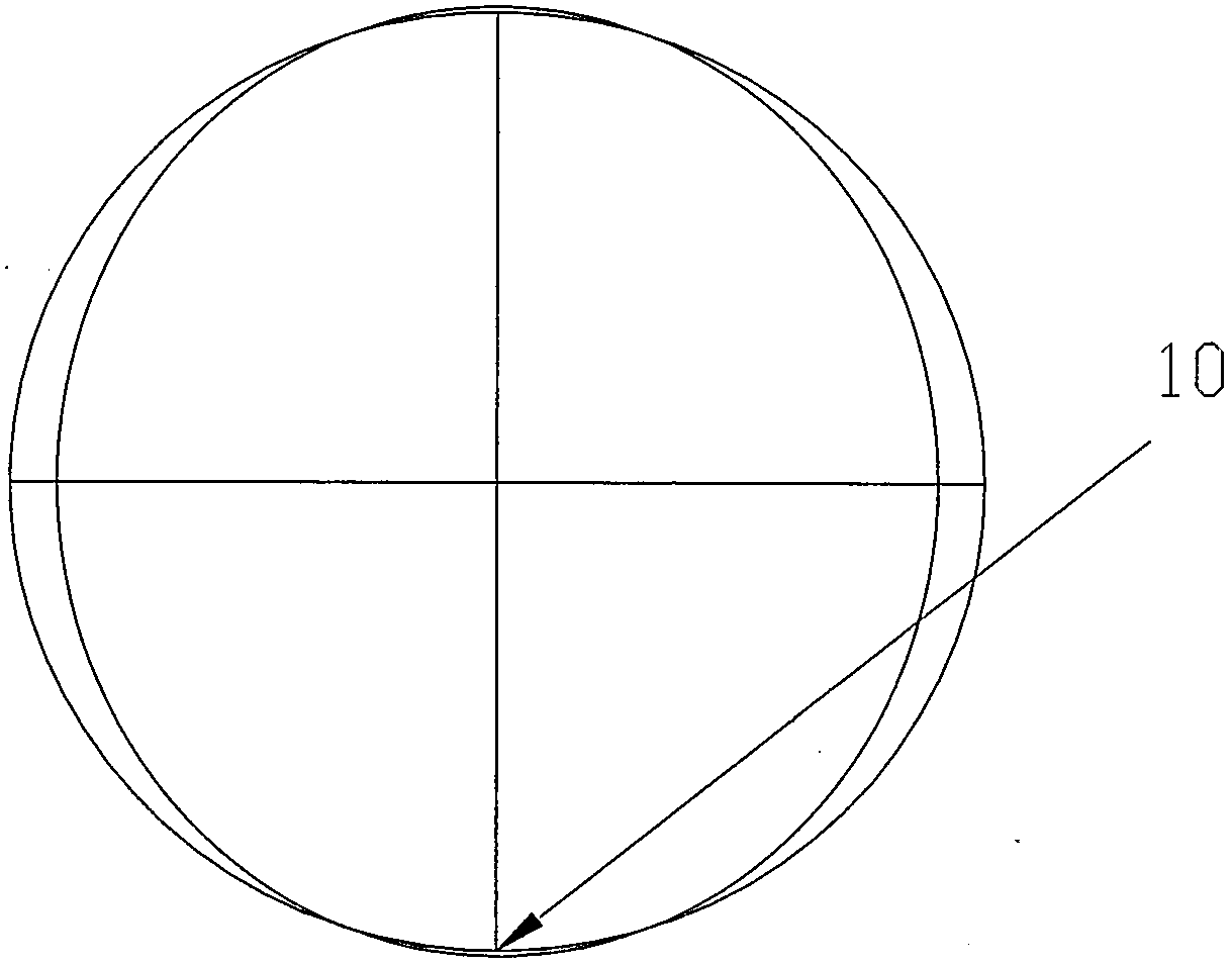
The invention relates to an axial vibration-resistant connector which is applicable as electricity and signal connectors by various cars, railway vehicles, new-energy cars, electric bicycles, motorcycles, industrial and mining machines, aircrafts and the like, especially for cars, railway vehicles and new-energy cars. The axial vibration-resistant connector is characterized in that a plug (20) and a socket (1) have an elliptical shape (21) and an elliptical shape (22), when long axles of the elliptical shape (21) and the elliptical shape (22) are in parallel, a plug (2) and a socket (1) are in clearance fit and can be freely plugged, when the long axles are perpendicular, the plug (2) and the socket (1) are in interference fit to be reliably contacted and have small contact resistance, a plurality of plugs (2) are arranged on a plug axle (4), and a plurality of sockets (1) are arranged on a socket housing (9), thus being capable of realizing connection among a plurality of circuits or electric signal lines with one-time installation.

Description

technical field [0001] The invention relates to a shaft-type vibration-resistant connector, which is suitable for use as electrical and signal connectors in various automobiles, rail vehicles, new energy vehicles, electric bicycles, motorcycles, industrial and mining machinery, and aircraft, especially for automobiles, rail vehicles and new energy vehicles. Background technique [0002] The connectors of automobiles and rail vehicles are used under the condition of vibration and shock. At this time, the electrical continuity of the contact pair is mainly considered when the electrical connector vibrates, shocks and collides under the specified frequency and acceleration conditions. The contact pair is in this dynamic stress condition. The phenomenon of instantaneous disconnection will occur under the condition, and the specified instantaneous disconnection time is generally 1 microsecond, 10 microseconds, 100 microseconds, 1 millisecond and 10 milliseconds. Taking the DC br...

Claims


Application Information

Patent Timeline
IPC IPC(8): H01R13/04H01R13/10H01R13/40H01R13/46H01R13/502H01R13/52H01R13/631H01R13/639H01R24/00H01R4/18
Inventor 邹政耀
Owner 邹政耀
Learn More