
Moisture-proof device for electrical equipment

A technology for electrical equipment and equipment, applied in the direction of non-electric variable control, instruments, control/regulation systems, etc., can solve problems such as labor-intensive and time-consuming, low service life of dehumidification heaters, and inability to monitor the temperature and humidity data of electrical equipment in real time. Improve work efficiency, promote safe operation, and reduce manpower and material resources

Active Publication Date: 2012-10-31
GUANGZHOU POWER SUPPLY BUREAU GUANGDONG POWER GRID CO LTD
View PDF6 Cites 8 Cited by
  • Summary
  • Abstract
  • Description
  • Claims
  • Application Information

AI Technical Summary

Problems solved by technology

[0002] The traditional moisture-proof treatment of electrical equipment is only to install dehumidification heating devices, temperature and humidity monitors and temperature and humidity sensors on the electrical equipment site, and display the temperature and humidity data in real time through the temperature and humidity monitors. When the humidity index is exceeded, the dehumidification heaters are all connected Generally, the service life of the dehumidification heater is generally low; in addition, the temperature and humidity data of electrical equipment cannot be monitored in real time. When the staff want to check the temperature and humidity status, they need to go to the scene to check, which is laborious and time-consuming;
[0003] To sum up, in the field of moisture-proof technology for power equipment, the existing electric power department is still unable to realize remote monitoring and temperature and humidity data analysis of dehumidification heaters, and has not yet formed a system management

Method used


Image

  • Moisture-proof device for electrical equipment
  • Moisture-proof device for electrical equipment

Examples


Embodiment Construction

[0014] The present invention will be described in further detail below in conjunction with the embodiments and accompanying drawings, but the embodiments of the present invention are not limited thereto.

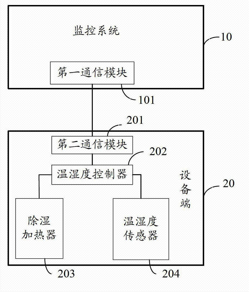
[0015] Such as figure 1 As shown, it is a structural schematic diagram of the moisture-proof device for power equipment of the present invention, including the equipment end 20, the equipment end 20 includes a temperature and humidity controller 202, a temperature and humidity sensor 204, a dehumidification heater 203, the temperature and humidity controller 202 and the temperature and humidity controller 202 The humidity sensor 204 is installed in the terminal box of the electrical equipment, and the temperature and humidity sensor 204 and the dehumidification heater 203 are both connected to the temperature and humidity controller 202;

[0016] The moisture-proof device for electrical equipment also includes a monitoring system 10, and the monitoring system 10 is provided ...


PUM


Abstract

The invention discloses a moisture-proof device for electrical equipment. The moisture-proof device comprises an equipment end, wherein the equipment end comprises a temperature and humidity controller, a temperature and humidity sensor and dehumidification heater, wherein the temperature and humidity controller and the temperature and humidity sensor are arranged in a the terminal box of the electrical equipment; the dehumidification heaters are connected with the temperature and humidity controller. The device also comprises a monitoring system, wherein the monitoring system is provided with a first communication module; the temperature and humidity controller is provided with a second communication module; the first communication module of the monitoring system is connected with the second communication module of the temperature and humidity controller; the monitoring system receives and saves the temperature and humidity data transmitted by the temperature and humidity controller; and the dehumidification heaters are controlled to input or withdraw through the temperature and humidity controller according to the temperature and humidity data. The moisture-proof system for the electrical equipment is managed, the dehumidification heaters can be remotely controlled in real time, and the temperature and humidity data is stored and managed.

Description

technical field [0001] The invention relates to a moisture-proof device, in particular to a moisture-proof device for electrical equipment. Background technique [0002] The traditional moisture-proof treatment of electrical equipment is only to install dehumidification heating devices, temperature and humidity monitors and temperature and humidity sensors on the electrical equipment site, and display the temperature and humidity data in real time through the temperature and humidity monitors. When the humidity index is exceeded, the dehumidification heaters are all connected Generally, the service life of the dehumidification heater is generally low; in addition, the temperature and humidity data of electrical equipment cannot be monitored in real time. When the staff want to check the temperature and humidity status, they need to go to the scene to check, which is laborious and time-consuming; [0003] To sum up, in the field of moisture-proof technology for power equipmen...

Claims


Application Information

Patent Timeline
IPC IPC(8): G05D27/02
Inventor 周强强莫文雄黄奕俊陈学东邹庆年方泽海林凯蔡楚荣李海成李党刘灿萍冯振宇
Owner GUANGZHOU POWER SUPPLY BUREAU GUANGDONG POWER GRID CO LTD
Learn More