
Rotation vehicle of crane

A technology for cranes and trolleys, applied in the direction of heavy-duty pulleys, load hanging components, transportation and packaging, etc., can solve the problems of decreased product competitiveness, increased use costs of cranes, hidden safety hazards, etc., and achieves improved safety factor, convenient and quick assembly, The effect of strong market competitiveness

Inactive Publication Date: 2012-10-31
TAIYUAN HEAVY IND
View PDF5 Cites 8 Cited by
  • Summary
  • Abstract
  • Description
  • Claims
  • Application Information

AI Technical Summary

Problems solved by technology

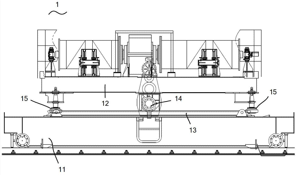
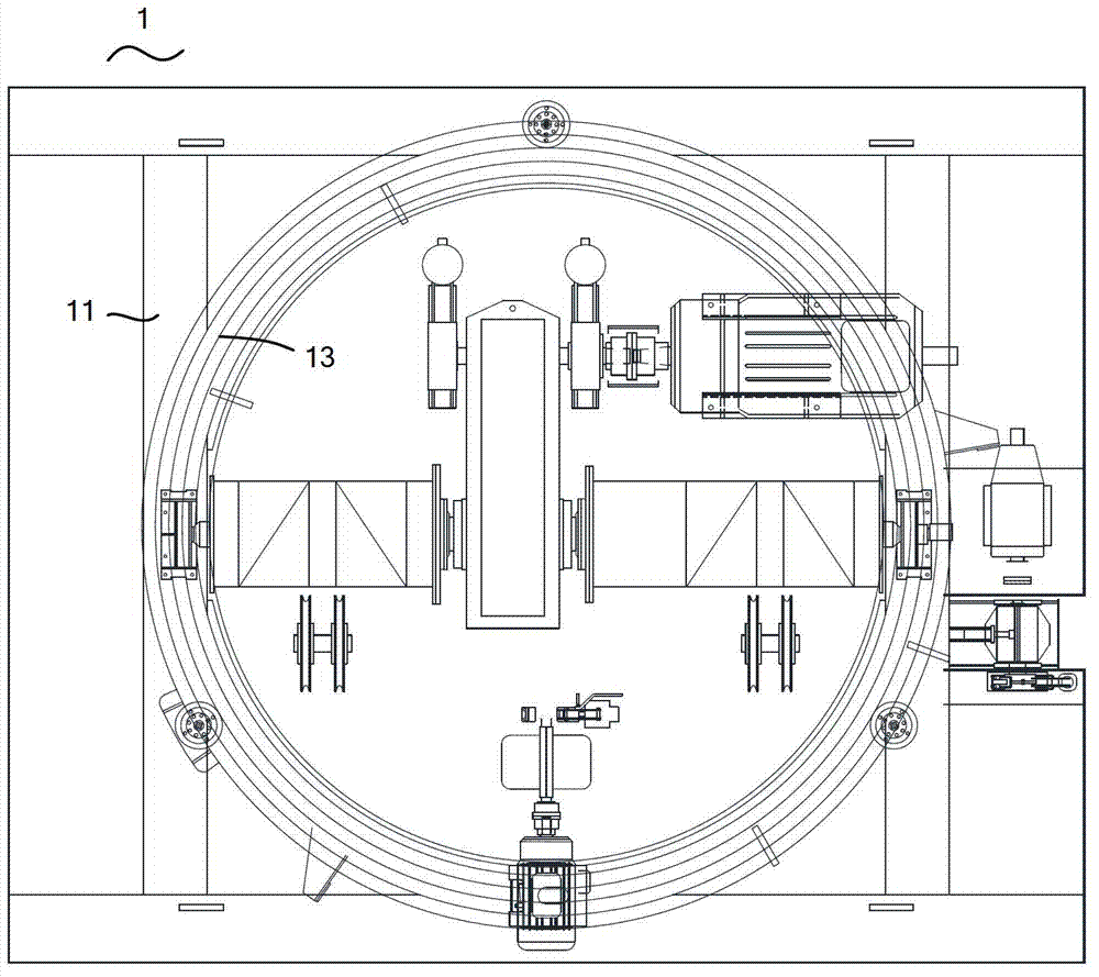
[0003] In the prior art, the overlapping arrangement of the wheels 14, the horizontal wheels 15, and the ring track 13 greatly increases the overall height of the crane slewing trolley 1, so the workshop also needs to increase the building height accordingly, objectively greatly increasing the cost of using the crane, and it is difficult to satisfy customers need to reduce costs
In addition, although the horizontal wheel 15 is installed on the upper trolley 12, it still cannot completely avoid the derailment of the wheel 14. Once the wheel 14 derails, a great potential safety hazard will be produced.
Finally, the manufacture of the wheels 14, the horizontal wheels 15 and the circular track 13 requires high precision and the assembly process is also very complicated, so the production cost of the crane slewing trolley 1 is greatly increased, and the product competitiveness is reduced

Method used


Image

  • Rotation vehicle of crane
  • Rotation vehicle of crane
  • Rotation vehicle of crane

Examples


Embodiment Construction

[0020] Typical embodiments embodying the features and advantages of the present invention will be described in detail in the following description. It should be understood that the present invention is capable of various changes in different embodiments without departing from the scope of the present invention, and that the description and drawings therein are illustrative in nature and not limiting. this invention.

[0021] Crane rotary trolley 2 structure of the present invention is as Figure 4-Figure 6 Shown, comprise top dolly 22, bottom dolly 21 and slewing mechanism. The upper dolly 22 is installed on the top of the lower dolly 21 by a slewing mechanism, and can rotate on the top of the lower dolly 21 by a slewing mechanism.

[0022] Such as Figure 4 to Figure 7 As shown, the slewing mechanism includes a driving device 23 , a pinion 24 , a matching supporting outer ring gear 25 , a supporting inner ring 26 and a plurality of rollers 27 . The driving device 23 inclu...


PUM


Abstract

The invention discloses a rotation vehicle of a crane. The rotation vehicle comprises an upper vehicle and a lower vehicle, and also comprises a rotation mechanism, wherein the rotation mechanism comprises a drive device, a small pinion, a support outer gear ring, a support inner ring and a plurality of rollers, the support outer gear ring and the support inner ring are matched with the small pinion, the drive device is installed on the lower vehicle, the small pinion is installed on an output shaft of the drive device in a rotary manner, the support outer gear ring is fixedly installed at the lower part of the upper vehicle and is meshed with the small pinion through an external gear, the support inner ring is fixedly installed at the upper part of the lower vehicle, and the plurality of rollers are clamped in a roller path jointly formed by the support outer gear ring and the support inner ring in a rolling manner. According to the rotation vehicle, the support inner ring is installed on the lower vehicle, the support outer gear ring is installed on the upper vehicle, the support outer gear ring can rotate relative to support inner ring under driving of the drive device and the small pinion and the guidance of the rollers, so that the upper vehicle can rotate relative to the low vehicle; and as the support outer gear ring and the support inner ring are assembled horizontally, the rotation mechanism is lower.

Description

technical field [0001] The present invention relates to cranes, in particular to the slewing of crane trolleys. Background technique [0002] At present, cranes are more and more widely used in large-scale factories and mines. Cranes walking on indoor cross-walls often need to be aligned with the hoisting position, which requires their trolleys to have a slewing function. Existing crane slewing trolley 1 structure such as Figure 1-Figure 3 Shown, be made up of top dolly 12 and bottom dolly 11, annular track 13 is installed on the upper plane of bottom dolly 11, wheel 14 and horizontal wheel 15 are installed in the bottom of top dolly 12. The wheel 14 cooperates with the ring track 13, and walks along the ring track 13 on the ring track 13. The horizontal wheel 15 is located outside the ring track 13. When the wheel 14 will derail, the outside of the horizontal wheel 15 abuts against the inside of the ring track 13 to play a limiting role. , Prevent wheel 14 from derailing....

Claims


Application Information

Patent Timeline
Patent Type & Authority Applications(China)
IPC IPC(8): B66C11/08
Inventor 王照锋王宏伟马强
Owner TAIYUAN HEAVY IND
Learn More