


Quick Research
Generate reliable direction feasibility study reports for your R&D in just a few steps.

Technical Q&A
Discover and master advanced knowledge NOW. Basics, ideas, possibilities, all at once.

Find Solutions
As an expert in R&D theories, this can generate solutions to your technical problems instantly.

Evaluate Feasibility
Analyze your overall solution with one click, know your potential R&D risks in advance.

Monitor Landscape
Get weekly tech updates, stay abreast of the latest tech innovations and key insights.
Semiconductor light-emiting element driver circuit and light fixture using the same
A technology of light-emitting elements and lighting devices, which can be applied to lighting devices, electrical components, electroluminescent light sources, etc., and can solve problems such as large output fluctuations
- Summary
- Abstract
- Description
- Claims
- Application Information
AI Technical Summary
Problems solved by technology
Method used
Image

Examples
Embodiment approach 1
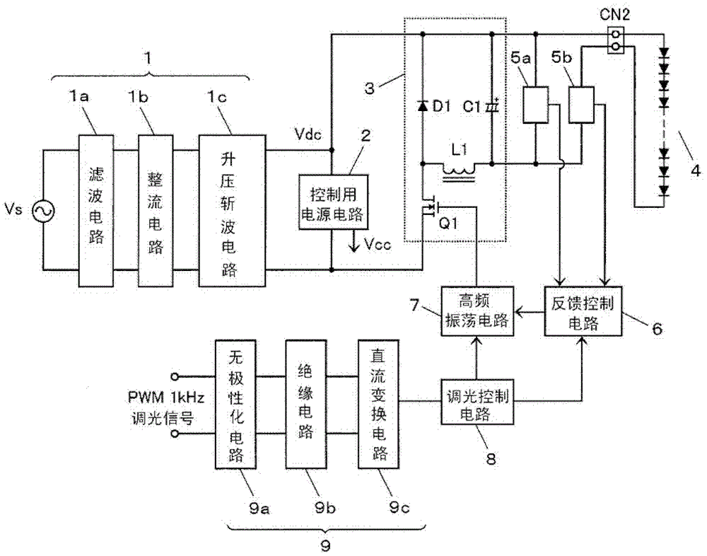
[0026] figure 1 It is a circuit diagram of a lighting device for a semiconductor light emitting element according to Embodiment 1 of the present invention. The input DC power supply 1 is composed of a filter circuit 1a, a rectification circuit 1b, and a step-up chopper circuit 1c, which rectifies and smooths the commercial AC power supply Vs, and outputs an approximately constant input DC voltage Vdc. The control power supply circuit 2 is, for example, composed of a step-down chopper circuit using an IPD element (refer to later-described Figure 4 ) configuration to step down the input DC voltage Vdc to generate the control power supply voltage Vcc.
[0027] The DC-DC converter 3 is a step-down chopper circuit (buck converter) composed of a switching element Q1, an inductor L1, a regenerative diode D1, and a smoothing capacitor C1. The switching element Q1 is turned on (ON) and turned off (OFF) at a high frequency. ), so as to output the input DC voltage Vdc after voltage co...
Embodiment approach 2
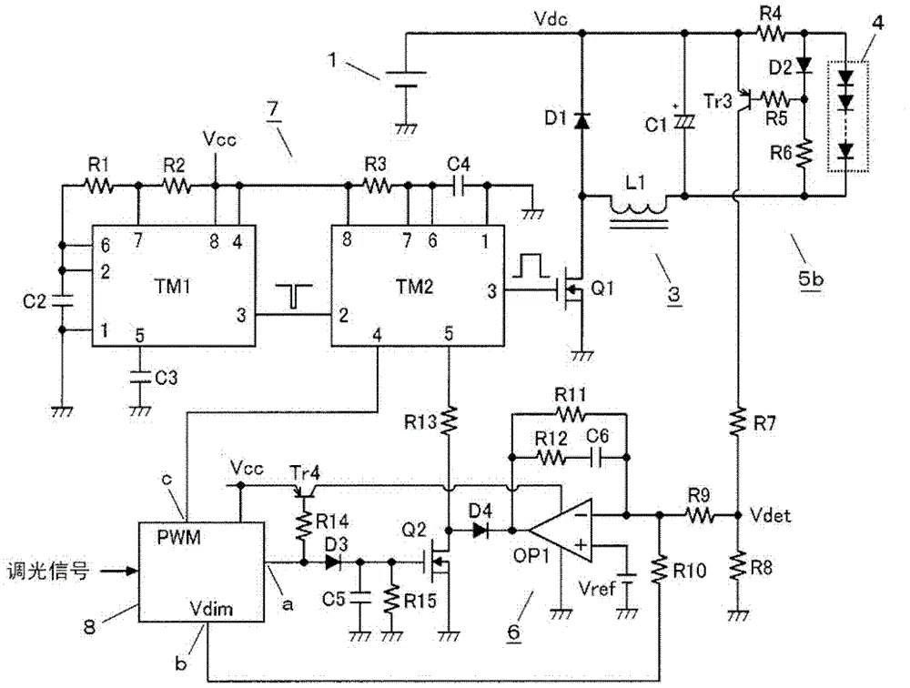
[0040] figure 2 It is a circuit diagram of Embodiment 2 of this invention. In this embodiment, it is more specifically expressed figure 1 The current detection circuit 5b, the feedback control circuit 6, and the high-frequency oscillation circuit 7 are configured.
[0041] "About High Frequency Oscillating Circuit 7"
[0042] The high-frequency oscillation circuit 7 is composed of general-purpose timer circuits TM1, TM2 and their peripheral circuits. The first timer circuit TM1 is an astable multivibrator that sets the on-off frequency of the switching element Q1, and the second timer circuit TM2 is a monostable multivibrator that sets the on-pulse width of the switching element Q1. device.
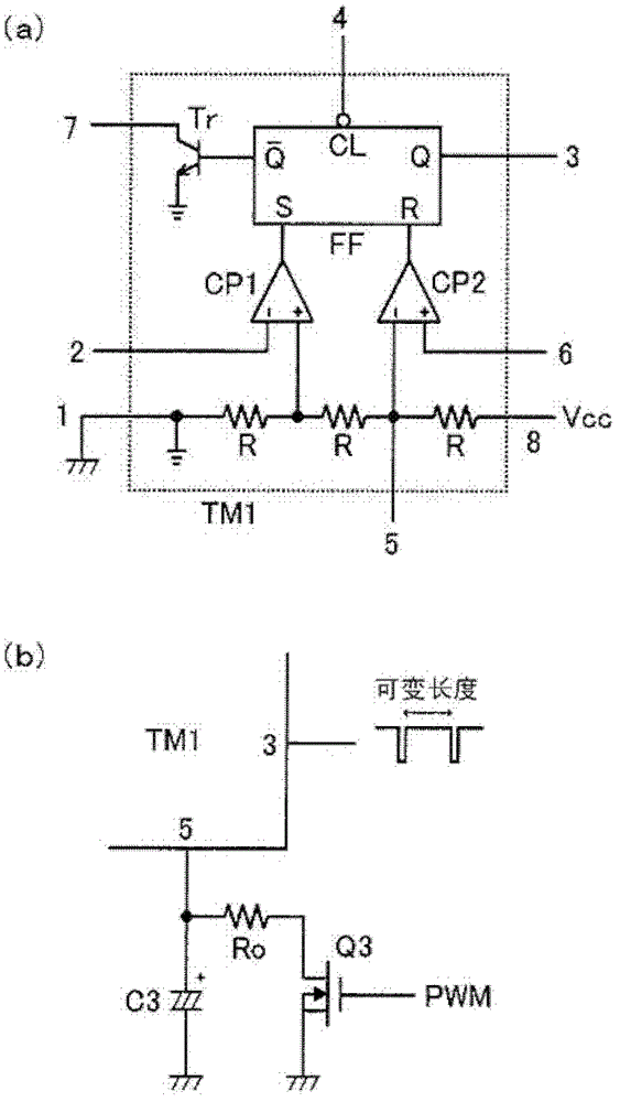
[0043] Timer circuits TM1, TM2 are with image 3 For a well-known timer IC (so-called 555) with the internal structure shown in (a), for example, the μPD5555 of Renesas Electronics (under the jurisdiction of the former NEC Electronics) or its dual version (μPD5556) or their substitu...
Embodiment approach 3
[0076] image 3 (b) has shown the main part structure of Embodiment 3 of this invention. In this embodiment, by figure 2 In the shown second embodiment, the voltage of the fifth pin of the first timer circuit TM1 is made variable in the low luminance range, and the frequency of the high-frequency on-off operation of the switching element Q1 is made variable.
[0077] In order to perform dimming and lighting to obtain an extremely weak light output as described above, it is advantageous that the frequency of the high-frequency on-off operation of the switching element Q1 is reduced as it approaches the dimming lower limit.
[0078] exist figure 2 In the preferred embodiment, since the voltage of the fifth pin of the first timer circuit TM1 is fixed, the frequency of the high-frequency on-off operation of the switching element Q1 is fixed. In contrast, in image 3 In the modified example shown in (b), the series circuit of the resistor Ro and the switching element Q3 is co...
PUM
 Abstract
Description
Claims
Application Information
 - R&D Engineer
- R&D Manager
- IP Professional
- Industry Leading Data Capabilities
- Powerful AI technology
- Patent DNA Extraction
Browse by: Latest US Patents, China's latest patents, Technical Efficacy Thesaurus, Application Domain, Technology Topic, Popular Technical Reports.
© 2024 PatSnap. All rights reserved.Legal|Privacy policy|Modern Slavery Act Transparency Statement|Sitemap|About US| Contact US: help@patsnap.com